SECTION 3 - VALVE AND INJECTOR ADJUSTMENT
Different procedures are used in setting injectors on STC
versus fixed timed engines. Refer to the Injector and
Valve Setting Chart (Figure 3-1) to determine the
crankshaft position when adjusting injectors and exhaust
valves.
Injector and Valve Setting- Crankshaft Position Chart
Bar in Direction Pulley Set Set
of Rotation Position Injector Valves
START A 3 5
ADVANCE TO B 6 3
ADVANCE TO C 2 6
ADVANCE TO A 4 2
ADVANCE TO B 1 4
ADVANCE TO C 5 1
Figure 3-1
1. If you did not previously position the crankshaft for
valve and injector adjustments, turn crankshaft clockwise
until the “A” mark on the accessory drive pulley is aligned
with pointer on the gear case cover.
2. At this point, the intake and exhaust valves should be
closed for cylinder No. 5 and the rocker levers should be
“loose”. The injector plunger for cylinder No. 3 must also
be at the top of its travel. If it is not, turn the crankshaft
another 360 degrees and realign the “A” mark with the
pointer.
Setting Injectors
Figure 3-2
Fixed Timing Control -
1. Set injector adjusting screws to 6 lbin. (0.7N*m) following
the setting chart (Figure 3-1). Cummins injector adjusting
tool (Part No. 3376592) may be used.
Figure 3-3
2. Tighten adjusting screw locknut to 45 lbft (60 N*m).
Step Timing Control -
A special tappet tool (Cummins No. ST-3822648) must be
used to set the STC style injectors. This tool has a small
locating pin that locates the tool in one of the four holes in
the tappet.
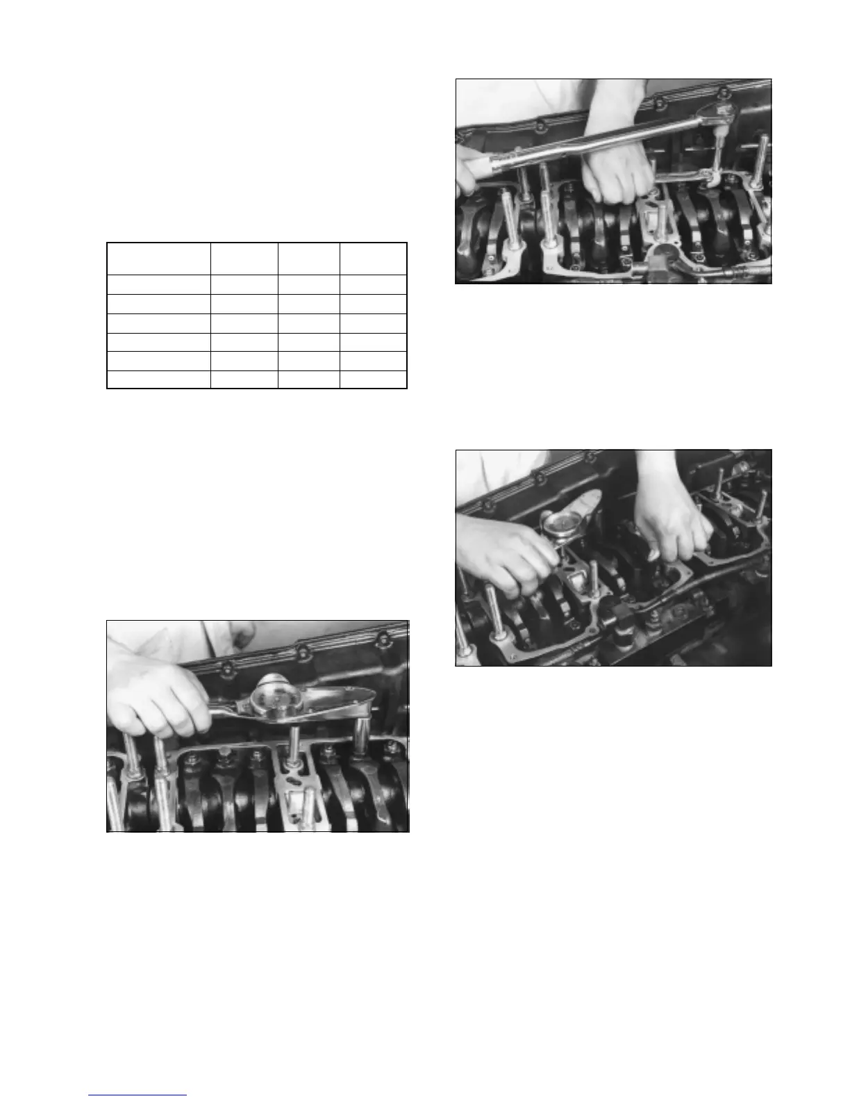
Figure 3-4
1. Place the tool on top of the tappet then rotate it until the
pin is inserted into one of the holes in the tappet. Apply
pressure to the tool handle in order to hold the tappet at the
maximum extended position.
2. Set the injector rocker arm adjusting screw to 5-6 lbin.
Remove tool before baring the engine to the next position
as indicated in the setting chart (Figure 3-1).
3. Tighten adjusting screw locknut to 45 lbft (60 N*m).
Setting Intake and Exhaust Valves -
1. Using the setting chart (Figure 3-1), adjust the valves
using a feeler gauge between the rocker lever and the
crosshead. The exhaust valve clearance should be 0.023"
and the intake valve clearance should be 0.011".
Note: Some engines may have different valve and
injector adjustments. Check the engine data plate to
verify settings.
2. Tighten adjusting screw locknut to 45 lbft (60 N*m).
3