SECTION 4 - INSTALLING THE BRAKE-
Figure 4-1
1. Install the engine brake housing gaskets. Make sure
that the oil supply slots align correctly with the oil supply
screws in the housings.
2. Before installing the brake housings, back out the
slave adjusting screws (located above the slave piston)
so that the slave pistons are fully retracted (up).
Figure 4-2
3. Place the engine brake housing on the rocker
housing. Check rocker levers to be sure there is no
interference.
Figure 4-3
4. If lifting or mounting brackets are used, install spacers
as required.
Figure 4-4
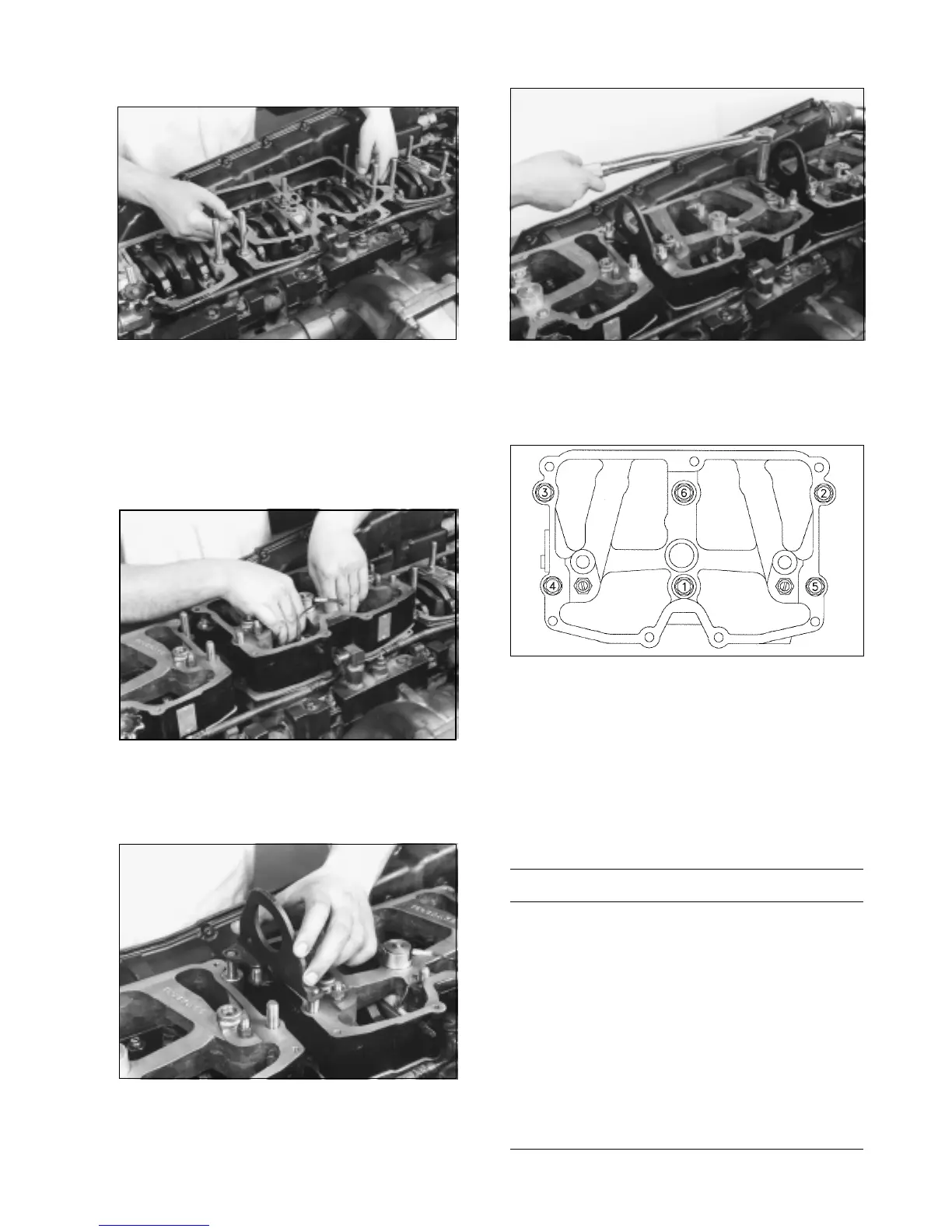
5. Install the nuts provided in the kit and tighten to 30 lbft
(40 N*m) in sequence as shown in Figure 4-5 then re-torque
to 60lbft (80M*m).
Figure 4-5
Slave Piston Adjusting Screw
Two adjusting screws are provided with the kit. Refer to the
Application chart shown in Figure 4-6 to identify which screw
should be used. The most commonly used screws (black)
are pre-installed in the brake. If the chart calls for the Beige
adjusting screw, they should be installed in place of the
other (black) screw.
APPLICATION CHART
ADJUSTING SCREW
CPL NO. ENGINE MODEL PART NO. COLOR
827 NTC400 88NT TB924921 BEIGE
838 NTC315 88NT TB924922 BLACK
840 NTC350 88NT TB924922 BLACK
910 NTC444 88NT TB924921 BEIGE
1185 NTC400 88NT TB924921 BEIGE
1187 FLEET 285 88NT TB924922 BLACK
1188 NTC350 88NT STC TB924921 BEIGE
1210 NTC444 88NT STC TB924921 BEIGE
1211 NTC400 88NT STC TB924921 BEIGE
1256 NTC444 88NT TB924921 BEIGE
1280 NTC444 88NT TB924921 BEIGE
1285 NTC444 88NT TB924921 BEIGE
1286 NTC444 88NT TB924921 BEIGE
1352 FLEET 300 88NT TB924922 BLACK
Figure 4-6
4