“Ultra IBEC” Ignition Battery Eliminator Users Manual
Copyright 2010 Tech-Aero Designs
www.tech-aero.net
2
Overview
Thank you for purchasing the Tech-Aero Designs “Ultra IBEC”. The Ultra IBEC eliminates the need to
carry the extra weight of a separate ignition battery and mechanical On/Off ignition switch in your
model. The Ultra IBEC offers better flight performance by not only reducing flying weight, but also by
assuring that a consistent supply voltage and robust current on demand is provided to the CDI ignition
module throughout the flight. The Ultra IBEC On/Off “kill switch” capability also enhances safety,
allowing control of ignition power to the engine the entire time the model aircraft is being operated.
When combined with the “failsafe” features that many radio control systems now provide, the Ultra
IBEC can be configured to kill ignition module power in the event that radio communications are
unexpectedly lost between the transmitter and receiver.
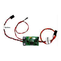
The Ultra IBEC plugs into a spare receiver auxiliary channel and provides switchable power to the CDI
ignition module from the receiver bus, while safely isolating the receiver and servos from high
frequency ignition noise that may be present on the wiring path between the CDI module and the Ultra
IBEC. The Ultra IBEC can also be connected to power bus expander products, provided that an
auxiliary channel capability is available at that connection point.
Please note that although the Ultra IBEC is highly effective at isolating the receiver and servos from
ignition noise that may be present in the wiring path between it and the CDI ignition module, it does not
eliminate the ignition noise that is always radiated by the CDI module itself and from the high voltage
wiring connection(s) to the engine sparkplug(s). This is the case with any and all ignition battery
eliminator and optical kill switch type products. Consequently, it is necessary to follow the installation
guidelines of the CDI ignition module and engine manufacturers to assure that adequate separation
exists between all parts of the receiver, servos, batteries and wiring. It is also necessary to assure, as
with any model ignition engine installation, that the shielding for the high voltage connections to the
engine sparkplug(s) are undamaged, and that proper grounding of the shielding to the engine case is
properly accomplished. Most modern CDI modules have the grounding built into the design of the
spark plug connector cap, but it is wise to assure that these connections are made correctly per the
manufacturer’s instructions.
To do its job most effectively, the twisted wire power connection from the Ultra IBEC to the CDI
module is purposely short, to assure that it is mounted near the CDI module. It has a long, twisted wire
lead to the receiver to allow installation with adequate separation from the receiver. Particularly in the
case of use with 72 MHz FM receivers, it is advisable to take full advantage of the length of wire
available on the receiver side connection, to assure adequate separation of any source of radiated
ignition noise from the CDI Module power connection side of the Ultra IBEC. Think of that as the
“dirty side”, whereas the wiring connection from the Ultra IBEC to the receiver is the “clean side”.
Note that the use of twisted wire helps reduce the antenna effect that exists with all electronics wiring.
This minimizes the pickup of ignition noise that is radiated by the CDI module high voltage output and
spark plug, and also limits the amount of re-radiated ignition noise that is present in the wiring directly
between the CDI module and the output power side of the Ultra IBEC.
From the radio receiver perspective, the Ultra IBEC behaves much as if it were just another high torque
servo. It is preset to switch CDI power ON at approximately the midpoint and higher “travel” setting for
the auxiliary channel it is connected to. Power to the CDI module will be switched OFF below that same
 Loading...