“Ultra IBEC” Ignition Battery Eliminator Users Manual
Copyright 2010 Tech-Aero Designs
www.tech-aero.net
3
midpoint auxiliary channel setting. Adjust the travel direction on the transmitter auxiliary channel
configuration to assure that the ON and OFF settings make logical sense for how the CDI module “Kill
switch” function will work, based on the direction of the lever or switch movement that you prefer.
Adjust the auxiliary channel ATV (travel endpoints) to 100% or more in each direction of travel, and be
sure that its sub trim is zeroed out (neutral). It is highly advisable to also set up a failsafe condition for
the Ultra IBEC auxiliary channel, so that if radio communications are lost, the Ultra IBEC can perform
its “Kill Switch” function to stop the engine. It’s easy to test this on the bench while setting up the radio
for this configuration, since the Ultra IBEC’s LED is illuminated when CDI power is switched ON.
The amount of current draw taken from the receiver flight pack battery is dependent on the brand/model
of CDI ignition module, the number of engine cylinders and the RPM that the engine is running at. As a
general rule of thumb, for a 10 minute flight, conservatively plan that approximately 100 to 120 MAh
per spark plug (2 cylinders max per each Ultra IBEC) will be drawn from the batteries to power the CDI
module. This will vary due to the design of the various CDI modules available, and with your flying
style. Higher average RPM’s during flight will always result in greater battery capacity usage than
lower average RPM’s. It is recommended that the battery capacity be monitored to determine the true
average usage of the combined load of servos and ignition module during a typical flight. As always,
pre-flight checks of battery condition are strongly advised. Never begin a flight without knowing that
there is adequate battery capacity to complete the flight with some reserve left over!
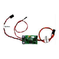
Installing and Configuring the Ultra IBEC
Figure 2 – Ultra IBEC Connection to Receiver and CDI Module
 Loading...