“Ultra IBEC” Ignition Battery Eliminator Users Manual
Copyright 2010 Tech-Aero Designs
www.tech-aero.net
4
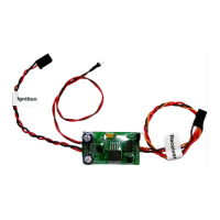
Please refer to Figure 2, which depicts the Ultra IBEC connected to an auxiliary channel of a
receiver. The Tech-Aero Ultra IBEC provides significant flexibility in your choice of supply voltage and
battery configurations. For example, dual redundant regulators and batteries are ideal to provide the
assurance that the entire flight pack and ignition module will continue to operate in the event of a single
battery, wiring, or even a regulator failure. Alternatively, the Ultra IBEC may be used in configurations
where the receiver and servos are powered by one or more unregulated NiCad or NiMh, A123, LiPo or
Li-Ion battery packs. NiCad or NiMh packs up to 8 cells may be used if desired, and up to 3 cell A123,
LiPo or Li-Ion battery packs may be used for power with the Ultra IBEC, provided that the rest of the
flight pack (receivers & servos) can tolerate such high voltages. The Ultra IBEC will take care of
providing the correct voltage to the CDI module via its jumper selectable voltage output feature. This is
a powerful feature that protects against obsolescence with the advent of high voltage (HV) technology
servos that are becoming more popular.
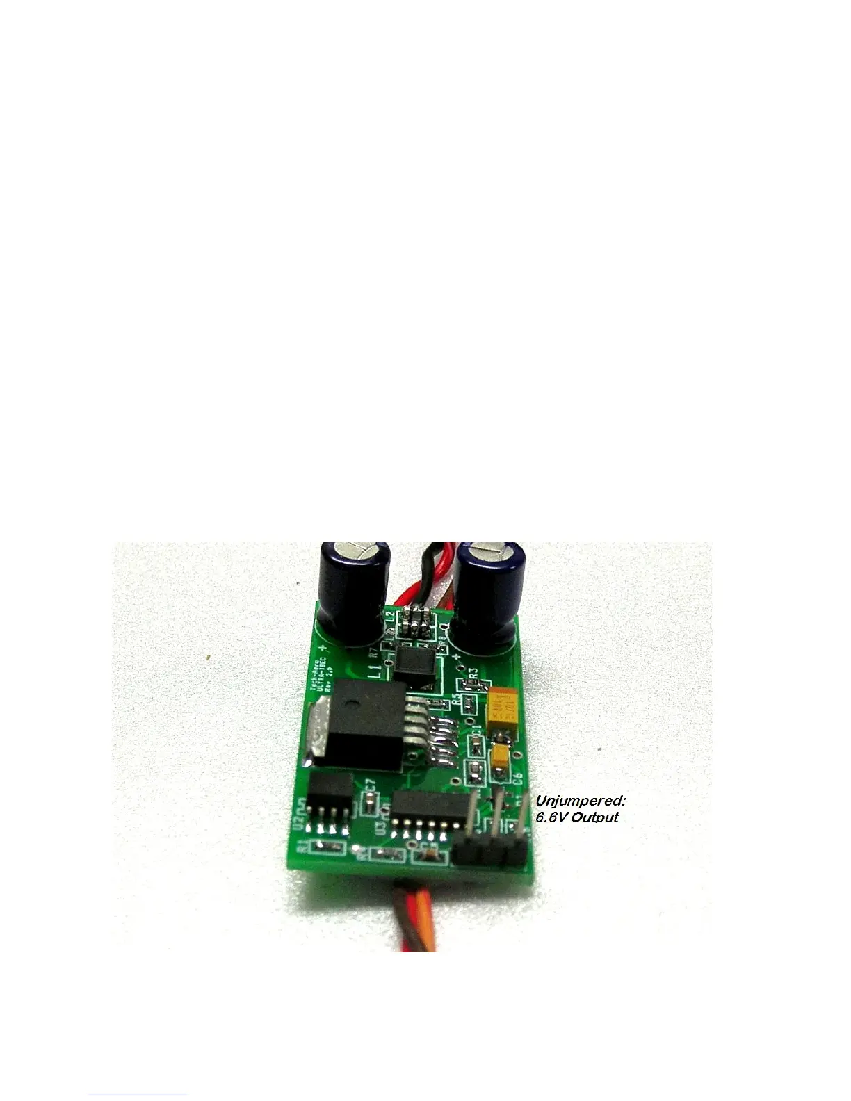
The voltage output from the Ultra IBEC is easily jumper configurable to safely meet the voltage
rating requirements of all popular model aircraft CDI modules. Please note however, that the voltage
output level of the IBEC will never exceed the voltage level being provided to it by the receiver’s power
bus. For example, if you want to power an ignition module that requires 6.5V or more, you would need
to not only configure the jumpers to the 6.6V setting, but would need to also assure that the receiver
power bus was configured with batteries (and perhaps regulators) that would provide a minimum of
6.7V. The reason for allowing a 0.2V margin of extra voltage at the receiver side vs. the CDI side is due
to the very small voltage dropout that will exist in the wiring and electronics during normal operation.
Figure 3 - Ultra IBEC 6.6V Jumper Configuration
 Loading...