GB
20
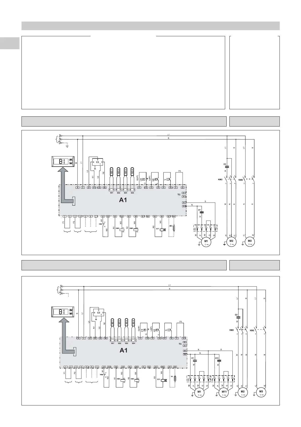
ELECTRICAL DIAGRAM - PHRT 9 - 230/1/50 10 05 793 - 01
Power
supply
230/1/50
Filter
Water inlet
Water outlet
Defrosting
External
On / Off
Hot / Cold
Alarm
Anti-freeze resistor
Fan Compressor Circulating pump
Controller
Interface panel
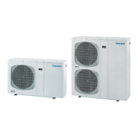
12 - WIRING DIAGRAMS
A1 Interface panel
B1 Controller
C1 M1 capacitor
C11 M11 capacitor
C2 M2 capacitor
C3 Filter
E1 High pressure switch
E2 Low pressure switch
EV1 Electrovalve
J1 Water differential pressure switch
KA1 Phase-sequence controller
KM2 Contactor compressor
KM3 Circulator contactor
M1 Fan
M11 Fan
M2 Compressor
M3 Circulating pump
R1 Anti-freeze resistor (accessory)
SD1 Water inlet probe
SD2 Water outlet probe
SD3 Condensation or defrosting temperature
probe
SD4 Outside air probe
Symbols of the components
B Blue
G Grey
M Brown
L Purple
P Pink
N Black
R Red
W White
Colours of the wires
ELECTRICAL DIAGRAM - PHRT 12 - 230/1/50 10 05 795 - 01
Power
supply
230/1/50
Filter
Water inlet
Water outlet
Defrosting
External
On / Off
Hot / Cold
Alarm
Anti-freeze resistor
Fan 1 Fan 2
Compressor Circulator
Controller
Interface panel