EasyManuals Logo

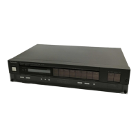
Technics QUARTZ ST-Z400L User Manual

Technics QUARTZ ST-Z400L
19 pages
To Next Page IconTo Next Page
To Previous Page IconTo Previous Page
Page #10 background imageLoading...
Page #10 background image
3
ey
£:
Tele)
&
m
MEASUREMENTS
AND
ADJUSTMENTS
Note:
AM
OSC
coil
(L203),
AM
IFT
(T201)
and
LW
antenna
coil
(L251)
have
been
already
adjusted,
and
require
no
adjustment.
AM
ADJUSTMENT
|
Setting
and
Equipment
used
.
AC
and
OC
electronic
voltmeters
(EVM)
5.
Output
of
signal
generator
should
be
no
higher
than
necessary
to
.
AM
signal
generator
(AM-SG).
obtain
an
output
reading.
.
Set
Band
selector
to
‘‘MW/LW”
position.
6.
Use
a
non-metal
screwdriver
for
the
adjustment.
.
Maintain
line
voltage
at
rated
voltage.
AM
SIGNAL
GENERATOR
DISPLAY
i
———
aan
FREQUENCY
PREPARATIONS
PARTS
ADJUSTED
|
ADJUSTING
PROCEDURE
CONNECTION
FREQUENCY
i
S
nat
aes
t
a,
I=
wecuntt
4
5,
23
a
:
Nae
MW-RF
ADJUSTMENT
_ *
Set
band
selector
to
“MW”
position.
612
kHz
Connect
AC
EVM
or
i
:
1.
Adjust
for
maximum
output.
1
(30%
Mod.
612
kHz
scope
to
“OUTPUT”
|
L202
(ANT.
Coil)
|
2.
Adjust
core
of
L202
by
Connect
AM-SG
to
-
with
400
Hz)
screwdriver.
AM
antenna
terminal
a
-
-
a
--
through
200
pF
1.
Adjust
for
maximum
output.
capacitor.
Common
to
1503
kHz
!
Connect
AC
EVM
or
cT201
2.
Repeat
steps
(1)
and
(2)
2]|
chassis.
(Weak
input)
©
(30%
Mod.
©
1503
kHz
scope
to
‘‘OUTPUT”
CANT.
-Teininien
until
the
frequency
correctly
with
400
Hz)
terminals.
:
:
matches
the
frequency
display.
terminals.
LW-RF
ADJUSTMENT
*
Set
band
selector
to
‘'LW"
position.
'
155
kHz
Connect
AC
EVM
or
!
1,
Adjust
for
maximum
output.
3
(30%
Mod
155
kHz
scope
to
“OUTPUT”
L252
(OSC.
Coil)
|
2.
Adjust
core
of
L252
by
Connect
AM-SG
to
with
400
Hz)
|
terminals.
screwdriver.
AM
antenna
terminal
-
pe
mee
eS
ares
=
3
ase
:
ot
through
200
pF
|
|
1.
Adjust
for
maximum
output.
capacitor.
Common
to
353
kHz
:
Connect
AC
EVM
or
CT251
.
2.
Repeat
steps
(3)
and
(4)
4]
chassis.
(Weak
input)
(30%
Mod.
353
kHz
i
scope
to
“OUTPUT”
until
the
frequency
correctly
(ANT.
Trimmer)
with
400
Hz)
|
;
terminals
FM
ADJUSTMENT
*
Setting
and
Equipment
used
Preparation
of
FM
signal
generator
(FM-SG)
FM
signal
generator
(FM-SG).
.
Apply
SG
output
to
antenna
terminal
of
the
set
through
75Q
Stereo
modulator.
FM
dummy
antenna.
Oscilloscope.
.
The
standard
input
of
the
set
is
60
dB
(1
mV),
400
Hz,
100%
AC
and
DC
electronic
voltmeters
(EVM).
modulation
[Because
of
using
dummy
antenna,
SG
output
must
Frequency
counter
(19
kHz
and
108
MHz
measurable).
be
12
dB
(4uV)
plus
(IHF).
That
is,
when
input
60
dB
(1
mV),
Low-pass
filter
(fe
:
15
kHz
~19
kHz).
SG
output
is
to
be
72
dB
(4mvV)].
Set
Band
selector
to
FM”
position
. .
Connect
stereo
modulator
to
FM-SG.
Set
FM
mode
switch
to
““mono”
position.
matches
the
frequency
display.
DNADTRON=
FM
SIGNAL
GENERATOR
DISPLAY
FREQUENCY
PREPARATIONS
PARTS
ADJUSTED
ADJUSTING
PROCEDURE
:
T
CONNECTION
FREQUENCY
FM-IF
ADJUSTMENT
heh
FM-SG
to
|
Connect
DC
EVM
to
Picuch
ISG
ENE
100.1
MHz
between
JGEE
(—)
Adjust
T101
core
so
that
5
2
(90%
Mod.
100.1
MHz
and
(+)
T101
(Discri.
IFT)
voltage
measured
in
signal
dummy
antenna.
: ' : :
with
400
Hz)
through
chock
coil.
mode
is
O
mV
in
300
mV
range.
(Apply
60
dB
(1
mV)
(Refer
to
Fig.
1)
to
antenna
terminal)
a
FM
MPX
V.C.0.
ADJUSTMENT
USING
A
FREQUENCY
COUNTER
USING
ALTERNATE
SYSTEM
.
100.1
MHz,
60
dB
Non-modulated
mono
signa!
applied
to
set.
(Fig.
2)
1.
Apply
stereo
signal
from
generator
or
stereo
station
to
tuner.
6
.
FM
mode
switch
to
‘‘auto”’
position.
2.
Adjust
VR301
until
stereo
indicator
lights
up.
Cement
arm
.
Connect
frequency
counter
to
through
resistor
(100k).
of
VR301
as
shown
in
Fig.
3.
.
Adjust
VR301
to
19
kHz
+
30
Hz.
SEPARATION
ADJUSTMENT
.
Set the
FM
mode
switch
to
Connect
FM-SG
to
“auto”.
FM
antenna
terminal
poe
as
oy
oe
.
Adjust
VR302
so
that
R
through
759
FM
Goce
Mesh
A
i
Had
a
0
output
is
minimized
when
dummy
antenna.
Doe
100.1
MHz
eset
fou
(Separation)
stereo
modulator
is
in
L
(Pilot
10%
Mod.
ee
i:
tie
)
akan
as
19
kHz)
(L
ch.
modulation)
mode
stereo
signal}
ae
i
Ay
and
that
L
pure
is
minimized
in
R
mode.
7

Questions and Answers:

Question and Answer IconNeed help?

Do you have a question about the Technics QUARTZ ST-Z400L and is the answer not in the manual?

Technics QUARTZ ST-Z400L Specifications

General IconGeneral
BrandTechnics
ModelQUARTZ ST-Z400L
CategoryTuner
LanguageEnglish

Related product manuals