EasyManuals Logo

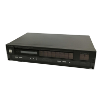
Technics QUARTZ ST-Z400L User Manual

Technics QUARTZ ST-Z400L
19 pages
To Next Page IconTo Next Page
To Previous Page IconTo Previous Page
Page #14 background imageLoading...
Page #14 background image
3s
ey
2:
Tele)
©
m
FUNCTION
OF
TERMINAL
(PLL
controller
IC901)
heey
Description
of
terminal
—>/
sane
FM
Signal
aaaep
/
seee>
AM
Signal
Segment
signal
output
terminal
for
display.
Common
signal
output
terminal
connected
to
LCD.
Output
is
delivered
in
3
values
of
ground,
1/2VDD
and
VDD
(at
5ms
intervals)
in
a
period
of
50
Hz.
The
segment
turns
ON
when
the
difference
in
voltage
is
+
Vpp
between
these
terminals
and
LCD1
~LCD23.
Power
supply
terminal
of
device.
Voltage
of
5V
+
10%
is
supplied
during
operation
of
device.
DD
=
To
hold
the
internal
data
memory
(RAM),
the
voltage
can
be
decreased
to
2.5V.
33
VDD
Note:
Pins
7
and
33
are
connected
inside
the
chip.
It is
unnecessary
to
supply
voltage
to
the
ai
pins.
C7
Input
is
local
oscillator
output
(VCO)
in
a
range
of
10
~
130
MHz
(0.3Vp-p,
min.).
8
EM
There
are
1/2
fixed
frequency
division
prescaler
and
2-step
(1/32,
1/33)
prescaler
internally.
Therefore,
when
deciding
the
frequency
dividing
value
of
programmable
divider,
it
must
be
decided
from
the
frequency
obtained
by
halving
the
local
oscillator
output
(VCO).
Input
is
local
oscillator
output
(VCO)
in
a
range
of
0.5
~
20
MHz
(0.1Vp-p,
min.).
9
AM
When
the
mode
is
shifted
to
FM,
the
AM
terminal
voltage
automatically
becomes
the
supply
voltage
of
device.
;
MW
ON
10
GND
Ground
terminal.
LW-—OFF
a
a
(re)
11
E01
When
the
divided
oscillator
frequency
is
higher
than
the
standard
frequency,
H-level
output
US
is
delivered
from
these
terminals.
12
E02
When
it
is
lower,
L-level
(OV)
output
is
delivered.
When
they
coincide,
it
results
in
floating.
+
a
Device
selection
signal
input
terminal.
The
signal
level
should
be
high
when
the
device
is
13
CE
operated,
and
low
when
not
operated.
With
this
terminal
shifted
to
low
level,
LCD
(liquid
crystal
display)
turns
off
and
the
memory
is
held.
14
NC
Not
used
in
this
unit.
15
x1
Connecting
terminal
for
crystal
oscillator.
The
crystal
connected
is
4.5
MHz.
16
X2
7
A3
(SD)
Terminal
to
put
in
stop
signal
during
auto
tuning.
The
voltage
is
5V
with
broadcast
received,
and
OV
without
broadcast
received.
This
is
the
interrupt
demand
signal
input
terminal.
The
signal
from
the
control
input
terminal
18
A2
(INT)
is
put
into
this
terminal,
demanding
for
interruption,
then
the
flow
of
program
will
be
unconditionally
shifted
to
the
address
No.
1.
19
A1
(FM)
FM/AM
output
terminal.
(FM
—®5V,
AM—®OV)
20
AO(LW/MODE)
Auto/mono
and
LW/MW
changeover
output
terminal.
(auto/MW—»
OV,
mono/LW
—>
5V)
21
K3
5.2msec
é]
ed
Input
terminal
for
key
return
signal
from
external
key
matrix.
24
KO
Gomsee
+
25
B3
5
emer
e
}
Output
terminal
for
key
return
signal
to
external
key
matrix.
28
BO
0
Bisse
29
C3
Terminal
for
FM
IF
ceramic
filter
frequency
compensation.
A
pulse
is
generated
when
the
voltage
of
terminal
13
rises.
<—
5.2msec.
30
C2
Output
terminal
for
key
return
signal
to
let
the
stereo
ay
indicator
light
up.
ov
31
C1
Nut
used
in
this
unit.
Muting
signal
output
terminal.
Muting
signal
is
delivered
during
operation
of
FM/AM
selector
32
co
:
, . : ;
switch
and
tuning
switch.
(4V
during
muting)
m
BLOCK
DIAGRAM
(MW
ANT
coil)
L202
(LW
ANT
coil)
L251
CF
IOI
CFIO2
Q101,102
FM-IF
amp.
1C1O!
AN7274NS
FM
IF
AMP/DET
AM
CONV
Ist
F
Limiter
(LW
_OSC|coil)
L252
a
6)
Q254
MW--ON
LW
-
OFF
AM
RF
signal
Q902,903,904
Loop
filter
(AM
IFT)
Q251
Mw—oFF
(7
LW+ON
CONTROL
+8)
6
i
ee
;
|
|
~h
|
CY
!
AMC+B)
9706
|
|
e
FMB)
“y
Q705
|
Ny)
|
|
8)
|
L
FM/AM
selector
Key
matrix

Questions and Answers:

Question and Answer IconNeed help?

Do you have a question about the Technics QUARTZ ST-Z400L and is the answer not in the manual?

Technics QUARTZ ST-Z400L Specifications

General IconGeneral
BrandTechnics
ModelQUARTZ ST-Z400L
CategoryTuner
LanguageEnglish

Related product manuals