EasyManua.ls Logo

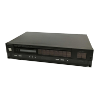
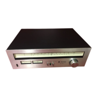
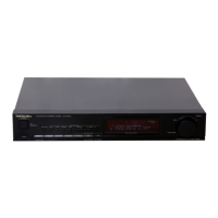
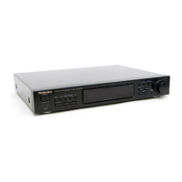
Technics QUARTZ ST-Z400L

Technics QUARTZ ST-Z400L
19 pages
To Next Page IconTo Next Page
To Previous Page IconTo Previous Page
Loading...
1C
301
AN7472S
FM
MPX
I9kHz
Output)
Q403,404
ORIVE
,707
[ol
ks)
SHING™:
SELECTOR)
ISO
ENER
062
ZENER
C+)
‘2SAI1015
SIGNAL
IND.
MPX
VCO
adj.
R313
Q402
2Scisis
SIGNAL
IND.
DRIVE.
Signal
Ind.
0403,404,405
LN446YP
SIGNAL
IND.
D701,
702
Q7ol
2S0882
REGULATOR
SVOSRIK2
Atzo1
C)
RECTIFIER
nm)
(re)
A
CJ
i
AC
LINE
220V
(50/60
Hz)
Ari
(2)
o
1
Tosa
[feowstreo
|
rp
C704
240V(
50/60
Hz)
0702
(3)-€a9)
Q702
2SCI8
15
REGULATOR
emer)
}
i
(o))
Pu
(LCD
LAMP)
m@
SCHEMATIC
DIAGRAM
(This
schematic
diagram
may
be
modified
at
any
time
with
the
development
of
new
technology.)
*The
part
No.
of
transistors,
IC
and
diodes
mentioned
in
the
schematic
diagram
stand
for
production
part
No.
Regarding
the
part
No.
with
@
mark,
the
production
part
No.
are
different
from
the
replacement
part
No.
Therefore,
when
placing
an
order
for
replacement
part,
please
use
the
part
No.
in
the
replacement
part
list.
*
This
is
the
basic
circuit
diagram
of
this
unit.
Note
that
part
of
the
circuit
is
subject
to
change
depending
on
the
areas.
Note
1:
1.
$17
:
Power
source
switch
in
“on”
position.
2.
$901
~
S908
__
:
Preset
tuning
switch.
*
With
it
momentarily
pushed
(less
than
0.4
sec.)
and
released,
the
1
~8
CH
are
received.
*
With
it
continuously
pused
(0.4
sec.
or
more)
and
released,
the
9
~
16
CH
are
received.
3.
$909
:
FM
selector
switch.
4.
$910
:
MW/LW
selector
switch.
5.
$911
:
Memory
set
switch.
(manuals
auto
memory)
6.
$912
:
Tuning
(down)
switch.
-
[down:
tuning
to
lower
frequency]
7.
$913
:
Tuning
(up)
switch.
[up:
tuning
to
higher
frequency]
8.
$914
:
FM
mode
switch.
(stereo
«+
mono)
9.
Indicated
voltage
values
are
the
standard
values
for
the
unit
measured
by
the
DC
electronic
circuit
tester
(high-impedance)
with
the
chassis
taken
as
standard.
Therefore,
there
may
exist
some
errors
in
the
voltage
values,
depending
on
the
internal
impedance
of
the
DC
circuit
tester.
*
Figures
in[____]stand
for
DC
voltage
in
FM
signal
(no
signal)
reception
.
mode.
*
Figures
in™
_,stand
for
DC
voltage
in
FM
stereo
signal
reception
mode.
*
Figures
in
(
)
stand
for
DC
voltage
in
MW
reception
mode.
*
Figures
in
[ ]
stand
for
DC
voltage
in
LW
signal
reception
mode.
10.
-
Positive
voltage
lines
&
AF
signal
lines
c—>FMsignal
cooot>FM
IF
se
>AM
signal
mame
AM
IF
11.
Important
safety
notice.
Components
identified
by
AV
mark
have
special
characteristics
important
for
safety.
When
replacing
any
of
these
components,
use
only
manufacturer's
specified
aprts.
Note
2:
e
Use
of
ceramic
filters
in
pairs
The
ceramic
filters
(CF
101,
CF
102)
for
FM-IF
circuit
are
available
in
three
ranks.
For
this
machine,
be
usre
to
use
the
ceramics
of
the
same
rank
in
a
pair.
At
rapairing
and
replacement,
pay
close
attention
to
the
diodes
(D901,
D902)
for
use
as
different
diodes
must
be
used
depending
on
each
rank
of
the
ceramic
filters.
Color
marking
RANK
(Color)
SFE
10.7
MHZ
(
|
Note:
©
Mark
:
Diode
is
used.
X
Mark
:
Diode
is
not
used.
@
LIQUID
CRISTAL
DISPLAY
(LCD)
e
Common
terminal
(No.
1,
2)
AN7274NS,
AN7472S
-
oa
1
LN446YP
SVDKV1236Z
Al
KI
A2
Segment
==
iis
i
ad
fe
2SA722
2SC945
2SD882
2SA1015,
2SC1675
2SC1815
ongaany
f
@
BS
B
MA165
SVDSR1K2

Related product manuals