Do you have a question about the Technics SL-EH760 and is the answer not in the manual?
Technical specifications for the audio output and performance characteristics.
Technical specifications of the CD pickup mechanism, including wavelength.
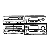
Overall physical dimensions and weight specifications for the unit.
Specific measures to protect the optical pickup from electrostatic discharge.
Procedures for effective grounding to prevent static electricity damage.
Method for grounding the work area and equipment for static prevention.
Step-by-step guide for inspecting the main Printed Circuit Board.
Step-by-step guide for inspecting the operation Printed Circuit Board.
Step-by-step guide for inspecting the CD servo Printed Circuit Board.
Detailed procedure for removing and replacing the traverse deck assembly.
Detailed procedure for removing and replacing the disc tray mechanism.
Procedures for disassembling and reassembling the mechanism base drive unit.
Step-by-step instructions for removing and replacing the motor assembly.
Steps to activate and understand error code displays for troubleshooting.
Method for performing servo adjustments and interpreting results.
Correlation of error codes with specific faults and troubleshooting steps.
Pinout and function details for the System Control IC (M38504M6200F).
Pinout and function details for the Servo Amplifier IC (AN8839NSBE2).
Pinout and function details for the Servo Processor IC (MN662790RSA).
Pinout and function details for the Motor Drive IC (AN8739SBE2).
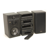
| Remote Control | Yes |
|---|---|
| Signal-to-Noise Ratio | 80 dB |
| Tuner Bands | FM, AM |
| Cassette Deck | Yes |
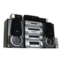
| Dimensions | 270 x 330 x 360 mm (Main Unit) |
| Weight | 7.2 kg (Main Unit) |