EasyManua.ls Logo

Technics SL-HD560E User Manual

Technics SL-HD560E
46 pages
To Next Page IconTo Next Page
Page #1 background imageLoading...
Page #1 background image
ORDER No.AD0203063C2
Compact Disc Player
SL-HD560E
Traverse Deck: RAE0152Z Mechanism Series
Colour
(N)...........Gold Type
System
SC-HD560:
Tuner; ST-HD560, Amplifier; SE-HD560,
CD Player; SL-HD560, Cassette Deck; RS-HD560,
Speakers; SB-HD560 (Made in Spain.)
SPECIFICATIONS
Specifications
1
Question and Answer IconNeed help?

Do you have a question about the Technics SL-HD560E and is the answer not in the manual?

Technics SL-HD560E Specifications

General IconGeneral
BrandTechnics
ModelSL-HD560E
CategoryStereo System
LanguageEnglish

Summary

Service Manual

SL-HD560E Traverse Deck Overview

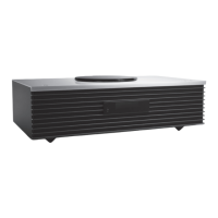
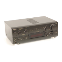
Details the specific CD player model and its traverse deck.

System Components Identification

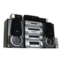
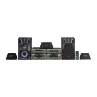
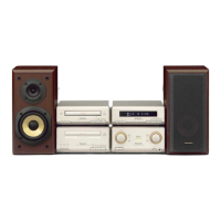
Lists the main components of the SC-HD560 system.

Product Specifications

Overview of the technical specifications for the unit.

Product Specifications

Audio and General Specifications

Details audio output, converter, sampling frequency, dimensions, and mass.

CD-R/RW Playback Limitations

Provides important notes on limitations for playing CD-R and CD-RW discs.

Service Notes and Precautions

System Interconnection for Servicing

Advises servicing the entire system due to interconnecting cables.

Traverse Deck Handling Precautions

Optical Pickup Static Prevention

Specific handling instructions to protect the optical pickup from static.

Electrostatic Discharge Prevention

Essential steps to prevent static discharge when handling components.

Laser Diode Safety Precautions

Work Table Grounding Procedure

Instructions for grounding the work surface to prevent static discharge.

Operation Checks and Component Replacement

Main P.C.B. Checking Procedure

Step-by-step guide for checking the main printed circuit board.

CD Servo P.C.B. Checking Procedure

Step-by-step guide for checking the CD servo printed circuit board.

Traverse Deck Assembly Replacement

FFC Board Removal Procedure

Spring Handling Caution

Warning about the importance of not losing small springs during removal.

Disc Tray Re-installation Guide

CD Servo P.C.B. Re-installation

Belt, Loading Motor, and Switch Replacement

Diagnostic Functions

Test Disc Preparation Note

Important note regarding the condition of the test disc for diagnostics.

Error Code Display Procedures

Error Code Troubleshooting Table

Table listing error codes, symptoms, and probable causes.

Servo Adjustment Procedures

Error Code Troubleshooting Guide

Pre-testing Checks

Essential checks to perform before starting diagnostic tests.

Power Supply and Schematic Notes

Schematic Diagram Modification Note

Note stating that schematic diagrams may be modified with technology.

Technical Diagrams Overview

Schematic Diagram

Diagram illustrating the electronic circuit layout.

Printed Circuit Board Diagram

Diagram showing the physical layout of components on PCBs.

Component Illustrations

Visual representations of ICs, transistors, and diodes.

Wiring Connection Diagram

Diagram showing how different components and PCBs are connected.

Block Diagram

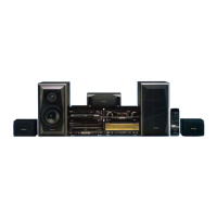
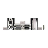
High-level diagram showing system components and their interactions.

Troubleshooting Guide

Guidance for diagnosing and resolving operational issues.

IC Terminal Functions

IC201 System Control IC Terminals

Terminal functions for the system control integrated circuit (IC201).

IC701 Servo Amp IC Terminals

IC702 Servo Processor IC Terminals

IC703 Motor Drive IC Terminals

Replacement Parts List

Replacement Parts List Details

Component Safety Marking Note

Information on components marked with a triangle indicating special characteristics.

Part Availability and Supplier

Details on part availability (Retention Time Limited) and supplier.

Cabinet Parts Location Diagram

Loading Unit Parts Location Diagram

Note on Non-Supplied Parts

Indicates specific items that are not supplied separately.

Schematic Diagram Format Note

Loading Mechanism Grease Application

Instruction to apply specified grease when changing loading mechanism parts.

Schematic Diagram-1

CD Servo Circuit Diagram

Detailed schematic of the CD servo circuit.

Connector Numbering Note

Explanation of connector numbering convention on schematic diagrams.

Schematic Diagram-2

Schematic Diagram-2 Sections

Loading Motor Circuit Diagram

Schematic detailing the loading motor circuit.

Main Circuit Diagram

Schematic of the main electronic circuit.

Operation Circuit Diagram

Schematic of the operation control circuit.

Overall Circuit Diagram

IC, Transistor, and Diode Illustrations

PCB Interconnection Diagram

CD Servo P.C.B. Connections

Details on the connections for the CD servo printed circuit board.

Loading Motor P.C.B. Connections

Details on the connections for the loading motor printed circuit board.

Main P.C.B. Connections

Details on the connections for the main printed circuit board.

Operation P.C.B. Connections

Details on the connections for the operation printed circuit board.

Front Panel Button Functions

Control Button Operations

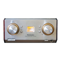
Details the specific functions of various control buttons like Play, Stop, etc.

System Block Diagram

System Block Diagram Details

Printed Circuit Board Layouts

CD Servo P.C.B. Layout

Component layout diagram for the CD servo PCB.

Loading Motor P.C.B. Layout

Component layout diagram for the loading motor PCB.

Main P.C.B. Layout

Component layout diagram for the main PCB.

Operation P.C.B. Layout

Component layout diagram for the operation PCB.

Related product manuals