EasyManua.ls Logo

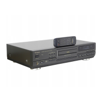
Technics SL-PG200A

Technics SL-PG200A
34 pages
To Next Page IconTo Next Page
To Previous Page IconTo Previous Page
Loading...
¢
1C801
(MN6474):
Digital
filter
and D/A
converter
0
Division
Command
load
input
(load:
L)
(Not
used,
connected
to
VDD)
MLD
Reset
terminal
Not
used,
connected
to
GND
RSTB
A
TP1
TP2
TEST
terminal
TEST
terminal
1
(connected
to
GND)
TEST
terminal
2
(connected
to
GND)
Not
connected
Not
connected
Power
supply
terminal
Lch
data
output,
(—)
terminal
EST1
N“N
|
EST2
z
(o)
z
?)
VDD4
OUTL
(-)
AVSS4
VSS3
OUTL
(+)
VDD3
= =
a/a]
oa
=
i]
wo}
Pp
Oo
>
A
GND
terminal
=
oa
ra
z
fe
>
>|
>
> >
< <
n
Oo
alae
OUTR
(+)
VSS2
20
21
22
23
OUTR
(—)
VDD1
DVDD1
—a/asfu
oOo;oirn
110
Division
Pde
GND
terminal
(digital
system)
Crystal
OSC
terminal
(33
MHz)
|
-
|
Not
connected
i
Power
supply
terminal
tin
GND
terminal
(digital
system)
Sub-strate
terminal
(Not
used,
connected
to
VDD)
=f
[=
faa
BCLK
Serial
bit
clock
input
SS
Serial
data
input
(MSB
first)
DVSS3
GND
terminal
(digital
system)
DVDD
——
Power
supply
terminal
|
39
|
seats
|
0
|
384fs
(16.9344
MHz)
output
40
Power
down
terminal
(Not
used,
connected
to
GND)
Mode
control
data
(Not
used,
connected
to
VDD)
Data
clock
for
MDATA
(not
used,
connected
to
VDD)
Mi
BLOCK
DIAGRAM
Note)
em
Audio
signal.
SERVO
CIRCUIT
|
MAIN
CIRCUIT
HF
/DI~D4
HF
/RFE
me
ligase
acmemmaiamenmerees
aura
(A
482220973234
DISC
FOCUS
MOTOR
LASER
DIODE
‘Hy
a
LASER
POWER
ADJ.
VR3520
DIODES
(4X)
HF
/DI~D4
POWER
SUPPLY
CIRCUIT
LM2940TSM
an~is,
891.893
POWE
Tl
Olin
17
AC
FI
POWER
IN
{oe
rnin
frecrine
FORME:
RAD
out
:
Current
output
of
integrated
(Re2—Re1)
input
currents.
BO~B3
:
Control
bits
for
radial
circuit.
DODS
:
Drop
out
detect
signal.
D1~D4
:
Photodiode
currents.
FE
:
Focus
error
signal.
FE
lag
:
Focus
error
signal
for
LAG
network.
HF
out
:
HF
amplifier
and
equalizer
voltage
output.
HFin
:
HF
current
input.
LM
:
Laser
monitor
diode
input.
LO
:
Laser
amplifier
current
output.
Re1
:
Radial
error
signal
1
(summation
of
amplified
currents
D3
and
D4).
Re2
:
Radial
error
signal
2
(summation
of
amplified
currents
D1
and
D2).
1
!
|
{
+5v
1
VR3569
FOCUS
ORIV!
<q
FOCUS
OFFSET
ADy.
-5v
SIGNAL
PROCESSOR
0008
-
035!
|
<4
—=—P¢
ECS/ECM
FE/
ae
si/
FElag
Rel
Re2
TL
PULH
RO
1
(
TOA8808T
)
PHOTO
DIODE
1
Ee
|
'
+
'
'
H
|
S
TURNTABLE.
———
x
MOTOR
.
RADIAL
MOTOR
—_—_
1
1
fl
|
RADIAL
DRIVE
<|
eos
|
482220972587
(TCAO3720P2)
t
00S
TL
out
f1c6503|
482220973235
.
ee
:
(TOABBOST
)
be
:
Sd
ae~s
RADIAL
ERROR
SIGNAL
PROCESSOR
an
ove
_
REDIG/XI
TRAY
SW
P42
~.P43
TRAY
SW
soot
i
KEY
MATRIX
TCAO372DM2R
(Active
Low).
MN6626
DIGITAL
SIGNAL
PROC
SUBO/SOCK
BLKCK
Civs
STAT
TRON
SMCK
if
!
4
Y
y
7
ry
if
HFD
SI/RD
CLVS
STAT
TRON
OSCI/
SUBQ/SQCK
Osc2
BLKC!
K
1C401
MNI8S7TIGI7PKJ
SYSTEM
CONTROL
SEGO~
SEGIS
(A~w
PP
FL6OI
Fi.
DISPLAY
P42~46
1G~12G
SEGO~15
MCLK
ECS/ECM
PC
SMCK
(OSC1/OSC2)
:
Key
:
FL
:
FL
:
Dai
:
Sul
:
Dat
:
Sut
:
Sul
:
Res
:
Tra
:
Tur
:
Tur
'
,0351
|
“ioron§
CONTROL
|
i}
OPERATION
CIRCUIT
RE
dig
:
Radial
error
digital.
(RE
DIG/X1)
RE
lag
:
Radial
error
signal
for
LAG
network.
Si/RD
:
On/off
control
for
laser
supply
and
focus
=
circuit.
TL
:
Track
loss
signal.
Div4
:
Radial
error
digital
devided
by
four.
HF/RF/ARF
_
:
RF
(Audio)
signal.
TRAY
SW
:
Disc
holder
open/close
det.
terminal.
CLVS
:
Spindle
servo
phase
synchro
signal.
STAT
:
Status
command
for
CRC
etc.
DMUTE
:
Data
mute
command.
MDATA
:
Mode
control
data.
MLD
:
Load
command
for
mode
control
data

Related product manuals