1I
FM
antenna terminal
is
as shown
belOW:
l
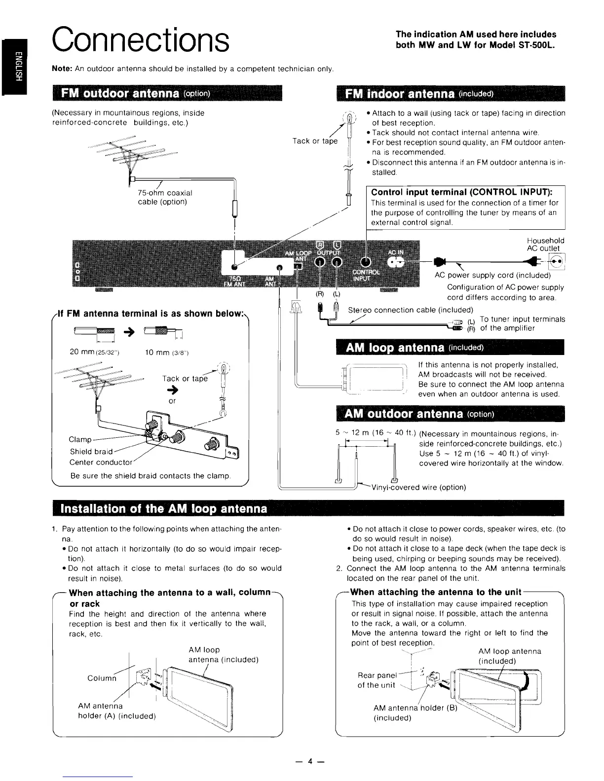
Be sure the shield braid
contacts
the clamp.
Stereo connection cable (included)
"--~..:::..~~~~~~~~~C~~~~·
(L)
The indication AM used here includes
both MW and
LW
lor Model ST-500l.
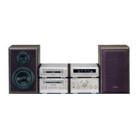
Connections
Note:
An
outdoor antenna should be installed by a
competent
technician only.
FM ouldoor antenna (option)
FM indoor antenna (included)
(Necessary
in
mountainous regions, inside
reinforced-concrete
buildings,
etc.)
75-ohm coaxial
cab
Ie
(option)
1
[J'"
LJBJ:=t
J
20 mm
(25/32
) 10 mm
(3/8
)
-
Clamp
Shield braid
Center
conductor
~'~(
T~
or tape I
or
~
----
Installalion of
Ihe
AM loop anlenna
1.
Pay attent ion to the following points when attaching the anten-
na.
• Do not attach it horizontally (to
do
so would impair recep-
tion).
• Do not attach it close to metal surfaces (to do so would
result
in
noise).
Wh
en attaching the antenna to a wal!, column
or
rack
Find the height and direction of the anten na where
reception
is
best and then fix
it
vertically to the wall,
rack, etc.
J~
AM
loop
antenna
(included)
_,.~.I
Column
i 6 >
,",,~.
i
AM anten na
holder
(A)
(included)
• Attach to a wall (using tack or tape) facing
in
direction
(.~-"
of best reception.
• Tack should not
contact
internal antenna wire.
Tack or tape
i:
• For best reception sound quality,
an
FM
outdoor anten-
/'/
i
na
is
recommended.
,.JJ.,
• Disconnect th is antenna if
an
FM
outdoor anten
na
is
in-
stalled.
Control input terminal (CONTROL INPUT):
This terminal
is
used for the connection of a timer for
the purpose
of
controlling the tuner by means
of
an
external control signal.
Household
AC
outlet
."
..
-~
AC
power supply cord (included)
Configuration of
AC
power supply
cord differs according to area.
To tuner input terminals
(R)
of
the amplifier
AM
loop anlenna (included)
If th
is
antenna is not properly instalied,
AM
broadcasts will not be received.
Be sure to connect the AM loop antenna
even when an outdoor antenna
is
used.
AM ouldoor antenna (option)
5
~
12 m (16
~
40
ft.) (Necessary
in
mountainous regions,
in-
side reinforced-concrete buildings, etc.)
Use5
-
12m(16
- 40 ft.) of vinyl-
covered wire horizontally at the window.
'nyl-covered wire (option)
• Do not attach
it
close to power cords, speaker wires, etc. (to
do
so would result
in
noise).
• Do not attach it close to a tape
deck
(when the tape
deck
is
being used, chirping or beeping sounds
may
be received).
2.
Connect the AM loop antenna to the AM 3ntenna terminals
located on the rear panel of the unit.
When attaching the antenna
to
the unit
---,
This type of installation may cause impaired recept ion
or
result
in
signa I noise. If possible, attach the antenna
to the rack, a wall, or a column.
Move the anten
na
toward the right
or
left to find the
point of best receptio
ll
.
AM
loop
anten na
(included)
-4-