o
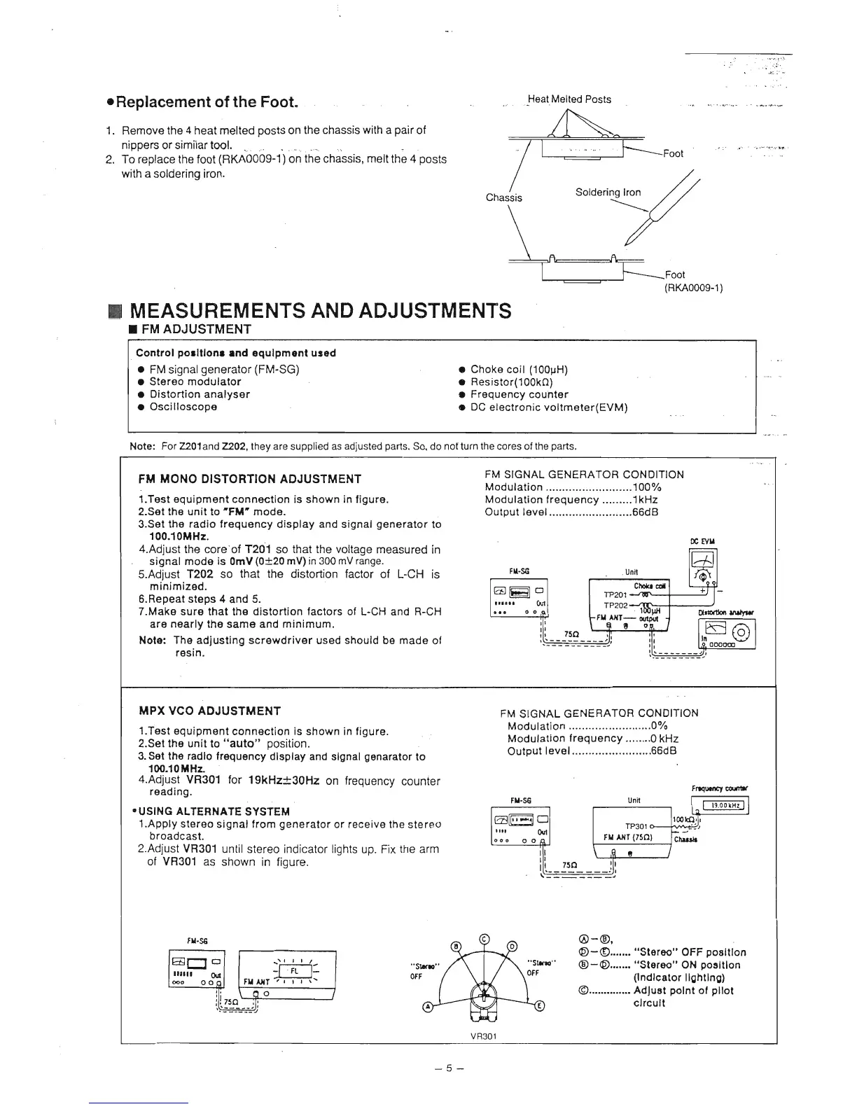
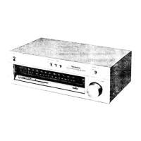
Replacement of the Foot.
1. Remove the 4 heat melted
posts
on the chassis
with
a
pair
of
nippers
or
similar tool.
2.
To replace
the Íoot
(RlG0009-1)
on
the
chassis'
melt
the 4
posts
with a
soldering
iron.
Foot
(RlG000e-1)
I
MEASUREMENTS
AND
ADJUSTMENTS
r FM
ADJUSTMENT
Conlrol
porltlonr
rnd
equlpmenl
ured
.
FM signalgenerator
(FM-SG)
o
Choke coil
(100pH)
I
Stereo modulator
.
Resistor(100k0)
o Distortion analyser o
Frequency
counter
o Oscilloscope
o DC
electronic voltmeter(EVM)
Note:
For Z201and7202,
they are
supplied
as
adjusted
parts.
So, do not
tum the
cores oÍ the
parts.
FM
MONO DISTORTION ADJUSTMENT
i.test equipment
connection
is
shown
in
íigure.
2.Set the
unit
to
'Fll'
mode.
3.Set
the
radio Írequency display and signal
generator
to
100.10MH2.
4.Adjust
the
core'ot T2O1 so that the voltage measured
in
signal mode
is
OmV
(0t20
mV) in 300
mV
range.
S.Adjust
T2O2
so that
the
distortion
factor
of L-CH is
minimized.
6.Repeat steps
4
and
5.
7.Make
sure
that
the
distortion
íactors
oÍ
L-CH
and R-CH
are
nearly
the same and
minimum.
Note:
The
adjusting screwdriver used should be made
oí
resin.
MPX VCO
ADJUSTMENT
1.Test
equipment
connection
is
shown in
Íigure
2.Set the
unit
to
"auto"
position.
3. Set the radlo frequency
dlsplay
and
slgnal
genarator
to
1fil.l0ilHz
4.Adjust
vR30í for
19kHzt3OHz
on
frequency
counter
reading.
.USING
ALTERNATE
SYSTEM
1.Apply
stereo
signal Írom
generator
or
receive
the
stereo
broadcast.
2.Adjust
VR301
until
stereo indicator lights
up.
Fix
the
arm
oÍ
VH301
as
shown in figure.
FM
SIGNAL GENERATOR
CONDITION
Modulation
..........................100%
Modulation
frequency
.........1
kHz
Output
level
.........................66d8
0c
EYra
m
FI_s6
. Unil
l /áÍ l
lag;l ffi
|:::'T.TJ
l,":iifu
ili
75o
l'_a"-T7
Ír_íal
;!*_==+==-Íl;
lll
llďo*o-v l
lll-:.//;
-
FM
SIGNAL
GENEBATOB CONDITION
Modulation
............. ............0%
Modulation
írequency ........0
kHz
Output |eve|........ 66dB
,-r*x-'
g
ffi
lralffiil ol I hmrolB-
l;-*l l- T:91*:
looo
""i'l
l
FllALÍ(7to)
lcu..r
w
ili__:s___:ll
-J-
-.
) ,o,
@-@,
O-O.......
"Storoo"
OFF
posltlon
@-@.......
"Storoo"
ON
posltlon
(lndlcator
llghtlng)
@..............
AdJuot
polnt
oí
pllot
clrcult
fr.s
-5-