EasyManua.ls Logo

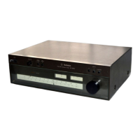
Technics ST-8080

Technics ST-8080
28 pages
To Next Page IconTo Next Page
To Previous Page IconTo Previous Page
Loading...
©
Connection
of
the
antenna
to
this
unit
(A)
If
300-ohm
connection
wire
is
used.
Turn
the
screws
of
the
antenna
terminals
2
or
3
times
counterclockwise
to
loosen
them,
connect
the
wire
to
the
terminals,
and
then
tighten
the
screws
once
again.
Note
that
the
antenna
connection
wire
between
this
unit
and
the
antenna
should
be
no
longer
than
necessary,
in
order
to
reduce
the
possibility
of
reception
of
unwanted
electric
waves
and
noise.
Terminal
screws
for
connection
of
300-ohm
antenna
L
SZ)
300-ohm
antenna
wire
(B)
If
75-ohm
coaxial
cable
is
used.
@)
Strip
off
about
20
mm
of
the
cover
of
the
coaxial
cable.
©)
Cut
off
about
10
mm
of
the
steel
wire,
and
then
fold
back
the
remaining
steel
wire.
©
Then
remove
all
except
about
7
mm
of
the
cover
of
the
core
wire.
@
Loosen
the
screw
of
the
ground
terminal,
connect
the
coaxial
cable
under
the
holder,
and
tighten
the
screw
once
more.
Be
sure
that
the
steel
wire
part
of
the
coaxial
cable
contacts
the
holder.
©
Finally,
connect
the
core
of
the
coaxial
cable
to
the
FM
antenna
terminal
(above
the
ground
terminal).
The
connections
are
then
complete.
@ ®
© @
Ground
Holder
terminal
>
T
About
About
7mm
20
mm
75-ohm
FM
antenna
;
terminal
coaxial
cable
Special
FM
antenna
(optional)
Terminal
screws
for
connection
of
75-ohm
coaxial
cable
Note:
ff
shielding
wire
and
core
are
short-circuited,
similar
condition
to
that
where
the
antenna
is
not
connected
is
established.
MINSTALLATION
OF
AN
ANTENNA
EXCLUSIVELY
FOR
FM
BROADCASTS
The
location
of
the
exclusive
antenna
for
FM
broadcasts
is
a
very
important
factor
in
the
determination
of
tone
quality,
and
even
the
best
antenna
will
not
function
satis-
factorily
if
it
is
installed
in
a
poor
location.
Carefully
consider,
therefore,
the
following
information
before
deciding
upon
the
location
where
the
antenna
will
be
installed.
(1)
if
such
obstacles
as
mountains
or
large
buildings
are
nearby,
broadcast
signals
which
are
reflected
from
these
obstacles
(reflected
waves)
will
cause
inter-
ference
in
the
broadcast
signals
which
are
received
directly
from
the
broadcast
station
(direct
waves),
resulting
in
multi-path
distortion,
which
will
cause
distortion
in
the
sound
and
poor
left-right
separation
of
the
sound.
Good
installation
prevents
multi-path
Obstacle
Reflected
waves
distortion
don't
enter
the
x
range
of
antenna's
oe”
a
sey
directional
oo
oy
characteristic
ra
"s/o,
o
@
"ey
Direct
wave
Broadcast
oneeeeeeens>
station
ates
Antenna's
directional
characteristic
(2)
In
order
to
prevent
automobile
ignition
noise
from
causing
interference,
the
antenna
should
be
installed
as
far
from
the
road
as
possible.
as
shown
in
figure.
In
addition,
it
should
be
installed
as
far
as
possible
from
neon
signs.
eum
Install
FM
antenna
away
from
sources
of
electrical
interference.
=
ied
(3)
It
should
be
installed
at
least
2
meters
or
more
away
from
a
metal
roof,
a
concrete
building,
or
from
any
other
antennas,
such
as
a
television
antenna.
(4)
FM
antennas
have
a
very
high
‘‘directional’’
charac-
teristic.
In
other
words,
they
are
much
more
sensitive
to
FM
signals
from
one
certain
direction,
more
than
from
any
other
direction.
The
antenna
should
be
install-
ed,
therefore,
so
as
to
face
in
that
direction
of
best
reception.
Although
it
is,
in
general,
true
that
the
higher
the
antenna
is
installed
the
better,
depending
upon
the
location,
it
may
be
that
a
lesser
height
would
be
even
more
advantageous.
However,
unless
there
are
some
special
conditions,
a
height
of
4
meters
above
the
ground
is
recommended.
(5
===>
if
antenna
is
too
@
low,
FM
broadcast
Install
FM
m=
reception
will
be
antenna
=
weak.
as
high
possible.
(6)
Be
sure
to
install
the
antenna
away
from
any
power
lines,
because
it
would
be
very
dangerous
if
the
antenna
were
to
fall
and
contact
the
power
lines.

Related product manuals