EasyManuals Logo

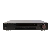
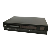
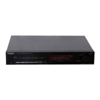
Technics ST-G470 Service Manual

Technics ST-G470
18 pages
To Next Page IconTo Next Page
To Previous Page IconTo Previous Page
Page #10 background imageLoading...
Page #10 background image
5
6
7
8 9
10
11
IAGRAM
arts
list
on
pages
19~21)
POWER
SWITCH
BI
PC.B.
SYSTEM
CONTROL
PC.B.
(S701)
[POWER
|
E
OPERATION
SWITCH
PC.B.
007
ay)
(
-MEMORY
/
)
(UP)
(DOWN)
(ON/OFF)
Cane?
)
—AUTO
MEMORY
|
MONO
!
PRESET
CHANNEL
EM-
EM-
SIGNAL
MODE
FM
mono
distortion
adj.
-AM/
)
“FM
/
)
(—aLLocaTion
—FREQ
SHIFT
BAND
SELECTOR
i,
0!
le
@l~
nN
D302
@BIX/c
q
oo
(L
ch)
(R
ch)
a
AM
[am
ant]
[FM
ANT
|
OUTPUT
LOOP
ANT
AM
ANT
FM
ANT
—14~—
m@
FUNCTIONS
OF
IC
TERMINALS
(IC902:
M50941-421SP)
PIN
NO.
|
IN/OUT
MARK
DESCRIPTION
OF
TERMINAL
ane
|
iNPUT
VREF
Reference
voltage
terminal.
Not
used
in
this
unit,
connected
to
GND.
SSL1
SSL2
7
INPUT
SSL3
FM
signal
level
detector
terminal.
8
INPUT
9
INPUT
|
STEREO
10
TUNING
O
17
TUNING
1
12
OUTPUT
|
IF
BAND
Station
detection
of
auto
tuning
terminal.
°
Received:
‘‘H’’,
No
signal:
“L”
Reference
voltage
terminal.
Not
used
in
this
unit.
11
——
|RF
BAND
Not
used
in
this
unit.
FM
IF
BAND
selector
terminal.
¢“normal”’:
“‘L”’,
‘super
narrow”:
“H”
13
NC
Not
used
in
this
unit.
14
—_—
REC
Not
used
in
this
unit.
Forcible
monaural
selection
terminal.
way
15
OUTPUT
|
MONO
|
.
Forcible
monaural
mode
Terminal
to
eliminate
shock
noise
due
to
unlocking
at
PLL.
<Muting
output>
«Pin
25
(CE)
is
“L"+"H"
or
“H"—="L”
16
OUTPUT
MUTE
*
Power
switch
“off”.
Frequency
change.
(up/down,
FM--AM
(MW/LW),
REC).
°FM
RF/IF
selection.
18
SRDY
PLL
data
output
terminal.
|
SRDY:
serial
1/O
enable
signal,
CLK:
clock
signal,
3
|
euEnuy
ans
SOUT:
serial
data
signal.
20
SOUT
21
INPUT
SIN
Control
input
terminal.
Clock
pulse
waveform
output
terminal.
22
OUTPUT
T1
°FM:
1kHz
signal
(duty
50%)
23
T2
Not
used
in
this
unit.
24
INPUT
inti
Remote
control
input
terminal.
Not
used
in
this
unit.
25
INPUT
Inve
Power
supply
detection
terminal.
eral
ised
oe
26
Ground
terminal.
*
-_
Vss
32
27
INPUT
RESET
Reset
signal
terminal.
28
INPUT
XIN
Connecting
terminal
for
crystal
oscillator.
29
OUTPUT
XOUT
30
_——
XCIN
Not
used
in
this
unit,
connected
to
GND.
31
—-
XCOUT
Not
used
in
this
unit.
33
—-
NC
Terminal
for
key
return
signal
34
RO
to
external
key
matrix.
36V
5
INPUT
s
|
|
|
37
R3
0
1V/2msec.
div
38
INPUT
vp
Power
supply
terminal
for
FL
display.
Segment
signal
terminal
for
ay
39
FL
display.
=
woos
roy
5
OUTPUT
=
54
S15
—26.0V
10V/Smsec.
div.
55
a
NC
Not
used
in
this
unit.
Terminal
for
key
scan
signal
ay
56
1
to
external
key
matrix
and
-f}-----
bas
grid
signal
terminal
for
FL
display.
Toviamses
div.
OY
Power
supply
terminal
of
device.
64
INPUT
Vec

Questions and Answers:

Question and Answer IconNeed help?

Do you have a question about the Technics ST-G470 and is the answer not in the manual?

Technics ST-G470 Specifications

General IconGeneral
BrandTechnics
ModelST-G470
CategoryTuner
LanguageEnglish

Related product manuals