EasyManuals Logo

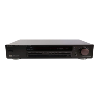
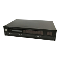
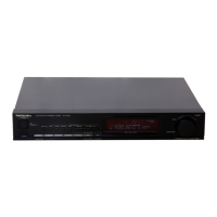
Technics ST-G470 Service Manual

Technics ST-G470
18 pages
To Next Page IconTo Next Page
To Previous Page IconTo Previous Page
Page #8 background imageLoading...
Page #8 background image
TIO!
Th
emer
tees
os
3.3¥
]3
3v
3.
3V
av
jisvils.4v
f4
avila
avifs.7v)
IS
28)
—(2?)
(26)
(5)
—(24)
C3
22)
MIF
M
MIX}
“|
AMF].
Lif_AMP|
ai
AMP.
11
FM
DET. Coil
=
cl13
Ko022
=
C4
35VI00
Fh
1c102
AN7274NS
P{BET]]
FM
if
AMP
@
DET
7AM
CONV
ay
o
AIEEN
-
FM
mono
distortion
ad)
ST-G470
ST-G470
1OK(B)}
C312
20022
R3i1”
vR302~1
12K
Q301
,
302
25D
|450RSTTA
2
R30!
C304
&
C30!
K3300P,
D301
af
22k
201
*
Fb
M/A
4082MTA
R306
82K
R305
82K
R335
3.9K]
|
&
how
R331
33K
9303
2SA1309AQSTA
R332
1K
TUNING
SWITCH
CIRCUIT
s92i
(TUNING
UP)
po
oe
Oo
$922
("own
DOWN
es
)
o-
o
s902__|s90!
(cH2)
(CHI)
G
OPERATI
ON
SWITCH
CIRCUIT
i
(13.6v)
p
ox
\
Sx
iB
ev
<2
id
By
és
Ee
tC)
R707
t33v
47K
(12
9V
5
s3ay
Q703
,
704
2SA1309AQSTA
POWER
SUPPLY
Q701,702
2SC3940AQSTA
-
REGULATOR
Faw
[Avov02
1SR35200T|B
wo
AF!
T400mA
5
0
OF
IK
15R36;
AN
‘An7o!
R701
C713
35100
+
C705
25VI000
a
MA4I4OMTIA
}—-t
C706
16V2200
+
L¢--.+~-----------------
D706,
MA4O62MTA
RC
GV
et
MAI65TA
|
SCH
EMATIC
DIAG
RAM
(Parts
list
on
page
19~21)
(This
schematic
diagram
may
be
modified
at
any
time
with
the
development
of
new
technology.)
Notes:
S701:
Power
switch
in
“‘on’’
position.
e$901~S910:
Preset
tuning
(39
channel
random
preset
tuning)
switches.
Judd
obcaranibilerean
pais
sed
ou
penis
oe
pa
path
The
ceramic
filters
(CF101,
CF
102)
for
FM-IF
circuit
are
available
in
three
$907:
CH7,
$908:
CH8,
$909:
CH9,
ranks.
For
this
circuit,
be
sure
to
use
the
ceramics
of
the
same
rank
in
a
pair.
$910:
CHO
At
repairing
and
replacement,
pay
close
attention
to
the
diodes
(D907,
D908)
e$911,
$912
Band
selectors
(band
selector)
switches.
for
use
as
different
diodes
must
be
used
depending
on
each
rank
of
the
$911:
FM,
S912:
AM
ceramic
filters.
S914:
FM
mode
selector
(FM-mode)
switch.
eS915:
FM
signal-strength
indication
(FM-signal)
switch.
S916,
S917:
Preset
channel
(preset
channel)
switches.
Color
marking
$916:
DOWN,
S917:
UP
(Red,
Blue
or
Orange)
eS918:
Memory
(memory)
switch.
$921,
$922:
Tuning
(tuning)
switches.
$921:
UP,
S922:
DOWN
SFE
measured
by
the
DC
electronic
circuit
tester
(high-impedance)
with
the
chassis
taken
as
standard.
Therefore,
there
may
exist
some
errors
in
the
voltage
values,
depending
on
the
internal
impedance
of
the
DC
circuit
tester.
Note:
©
mark:
Diode
is
used.
x
mark:
Diode
is
not
used.
o(
aa
):
AM
voltage
+Caution!
|
muting
voltage
IC
and
LSI
are
sensitive
to
static
electricity.
°
Positive
voltage
lines
(+)
Secondary
trouble
can
be
prevented
by
taking
care
during
repair.
Negative
voltage
lines
(—)
_“""*
AF
signal
+Cover
the
parts
boxes
made
of
plastics
with
aluminum
coil.
cae
FM
OSC
FM
signal
«Ground
the
soldering
iron.
saab
AM
OSC
=>
AM
signal
+Put
a
conductive
mat
on
the
work
table.
e|mportant
safety
notice
*Do
not
touch
the
legs
of
IC
or
LSI
with
the
fingers
directly.
Components
identified
by
A,
mark
have
special
characteristics
important
for
safety.
When
replacing
any
of
these
components,
use
only
manufacturer’s
specified
parts.
m@
TERMINAL
GUIDE
OF
IC’S,
TRANSISTORS
AND
DIODES
AN6554F
M7001
M50941-421SP
AN7274NS
|
AN74728
|
MA4062,
MA4082M
MA4140M,
MA4051M
MA4300M
2SA1309,
2SC3311
2SD1450,
DTC144ES,
2SA1253RSTAC
>
cg
28C1310,
2SC3940
MA165,
MA150FV
1SR35200
Anode
Anode
Cathode
Cao—tq-—0
A
Cathode
Cac—fe-—o
A
—12—
ap
vials
—a
FREQUENCY
e\|ndicated
voltage
values
are
the
standard
values
for
the
unit
a
ae
10.67
MHz

Questions and Answers:

Question and Answer IconNeed help?

Do you have a question about the Technics ST-G470 and is the answer not in the manual?

Technics ST-G470 Specifications

General IconGeneral
BrandTechnics
ModelST-G470
CategoryTuner
LanguageEnglish

Related product manuals