EasyManuals Logo

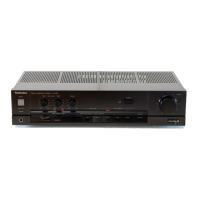
Technics SU-8055 X User Manual

Technics SU-8055 X
13 pages
To Next Page IconTo Next Page
To Previous Page IconTo Previous Page
Page #7 background imageLoading...
Page #7 background image
Earth
(Ground)
Lines
ke
ee
any
eee
ome:
[BASS]
[TREBLE
Sul
ee
SUBSONIC
FILTER]
[PHONO]
HIGH
FILTER]
[100K(0)x2
100K
(C)x2
me
T
|
as
a
Sanna
lial
dad
cant
Campi
LOUDNESS
C828
CURRENT
MIRROR
QI01,
102
PHONO
INPUT
AMP.
\
Q401
411,412
x
;
0402
a408
85
2SA798A
2SA564
2SATIBA
eSCI8i5
VE
DIFFERENTIAL
CURRENT
STABILIZER
DIFFERENTIAL.
EMITTER
FOLLOWER
ae
a
Bes
104
2SCI885
EQUALIZER
AMP
PRE
DRIVE
€401,402
»TKOOSON
Qs501
Qso2
2SA6B4NCE
2SD762
REGULATOR
REGULATOR
\
f
ON
POWER
PACK
oe
Q105,106
\_
2SAiol
EQUALIZER
AMP
=
<4
=e
Oo
=
=
= i
i
70
!
Pes
S
|
bo
oR
PLAYBACK]
[REC
OUT]
[PLAYBACK]
[REC
OUT]
AUX
GROUND]
REC/PLAY
Ww
Lape
veck2!
Lape
DECK
TAPE
DECK
|
J
(SPEAKER
CIRCUIT
PROTECTION
FUSES)
[9]
BALANCE
VOLUME
Notes:
1.
$1:
Input
selector
switch
in
‘‘PHONO”
position.
@
TAPE
2
<>
@
TAPE
1<—»
@
PHONO
<>
@
TUNER
<>
@)
AUX
2.
$2:
Recselector
switch
in
"OFF"
position.
@
TAPE
2h1
<>
@
TAPE
12
<>
@
OFF
<«—>
©
PHONO
<>)
TUNER
<—>
AUX
3.
$3:
High
filter
switch
in
“OFF”
position.
4.
S4
_
:
Loudness
switch
in
OFF”
position.
5.
$5
:
Phono
MM/MC
cartridge
selector
switch
in
‘‘MM"
position.
6.
S6_
:
Subsonic
filter
switch
in
“OFF”
position.
7.
$7:
Range
switch
in
‘’X1"'
position.
8.
S8
:
Meter
light
selector
switch
in
“DIMMER”
position.
9.
SQ:
Speaker
switch
in
“MAIN”
position
10.
$10
:
Power
switch
in
“ON”
position.
11.
$11
:
Voltage
adjuster
switch
in
“240V”
position.
(240V
<>
220V
<>
120V<>
110V)
12.
Indicated
voltage
values
are
the
standard
values
for
the
unit
measured
by
the
DC
electronic
circuit
tester
(high
impedance)
with
the
chassis
taken
as
standard.
Therefore,
there
may
exist
some
errors
in
the
voltage
values,
depending
on
the
internal
impedance
of
the
DC
circuit
tester.
(-]
Standards
values
)
Bright
13.
The
mark
has
been
used
for
the
indication
of
specified
parts
for
an
assurance
of
safety,
but
it
has
been
changed
to
A
mark.
When
replacing
parts,
be
sure
to
use
paris
with
correct
numbers
with
reference
to
the
circuit
drawing
or
the
repair
parts
list.
—>
A
(new
mark)
14.
To
represent
transistors,
@
is
used
instead
of
TR
(Ex.
TR1
—™
Q1)
15.
Phono
signal
lines
of
left
channel.
16.
This
schematic
diagram
may
be
modified
at
any
time
with
the
development
of
new
technology.
m@
BLOCK
DIAGRAM
oureur
ouTPuT
output
f-See4eeesee
waa
nao
5
5
5-77
-
+--+
--
75-5
~~~
-------
INPUT
-Vec
1C601,
602
(SVIBA663)
FL
Comparator
1C401,
402
(SVISTKOO50N)
Power
Amplifier
1C201
(SVINJM4559DS)
Tone
Amplifier
2SA798A
SVIBA663
2SA1015
281815
2SA684NCE
2SA564
2SC828
2SC1885
4
“15
a
1392
gy
He
:
2801913

Questions and Answers:

Question and Answer IconNeed help?

Do you have a question about the Technics SU-8055 X and is the answer not in the manual?

Technics SU-8055 X Specifications

General IconGeneral
BrandTechnics
ModelSU-8055 X
CategoryAmplifier
LanguageEnglish

Related product manuals