Do you have a question about the Technics SX-P30 and is the answer not in the manual?
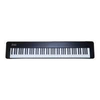
Details on the keyboard, polyphony, and sound capabilities like piano and electric piano.
Information on control functions like reverb, volume, tune, and other connections.
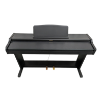
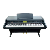
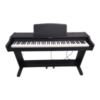
Specifies power requirements, physical dimensions, and net weight of the instrument.
Lists the accessories that come with the product, such as music stand and AC adaptor.
Follow labeled precautions, use specified parts, proper wiring, and avoid contact with heat-emitting devices.
Unplug power, use specified parts, check power cord, restore lead dress, and perform insulation resistance test.
Procedure for testing insulation resistance between the AC plug and exposed metal parts.
Details on MIDI, LINE OUT, DC IN, and Headphones terminals for connectivity.
Information on keyboard functionality, indicator, tune, sound selection, reverb, play button, and volume.
Instructions for connecting the AC adaptor to the instrument and a power outlet.
Guidance on connecting the piano to stereo sets or speakers via LINE OUT.
Diagrams identifying the locations of Main, Jack, MKB1, and MKB2 PCBs.
Step-by-step guide to removing the bottom cover of the keyboard.
Procedure for detaching the MAIN printed circuit board.
Instructions for safely removing the entire keyboard unit.
Detailed instructions for removing and reassembling individual keys, including notes on potential breakage.
Steps for detaching the JACK printed circuit board from the unit.
Diagnoses and remedies for situations where no sound is produced.
Troubleshooting MIDI data transfer problems, including channel matching and demonstration mode.
Guidelines for accurately measuring output waveforms using specific equipment and probes.
Highlights components with special safety characteristics and the need for specified replacement parts.
Explanation of symbolic marks used for resistors and capacitors in schematics.
Diagram showing the component layout on the component side of the MAIN PCB.
Diagram showing the foil (solder side) layout of the MAIN PCB.
Illustrates measured waveforms at specific test points under self-diagnostic mode.
Diagram showing the component and foil layout for the JACK PCB.
Diagram showing the component and foil layout for the MKB1 PCB.
Diagram showing the component and foil layout for the MKB2 PCB.
Lists replacement parts for PCBs and integrated circuits.
Replacement transistors, diodes, oscillators, and coils.
Replacement jacks, switches, and variable resistors.
Replacement parts for the MKB1 and MKB2 manual keyboard circuits.
Replacement wiring components and connectors.
Diagram showing the location of various parts within the main cabinet assembly.
Diagram illustrating the arrangement of parts in the manual keyboard assembly.
General replacement parts for the cabinet, including diodes and plugs.
List of replacement parts for the sustain pedal and various fasteners.
List of individual key components, springs, and related parts.
List of packing materials used for shipping the product.
Details about the operating instruction manuals included with the product.
| Brand | Technics |
|---|---|
| Model | SX-P30 |
| Category | Musical Instrument |
| Language | English |