SL-12
Installation, Operation and Maintenance
Page 7
30)
Extend the footpad to both extents and apply
anti-seize to the three retaining rings and
where the double screw makes contact with
the base of the footpad.
ELECTRICAL
31) Refer to Fig 10 Wiring Diagram for all steps
under this heading.
Single Phase
32) Connect the Overhead Limit Switch Cord to
Power Unit as shown.
33) Connect Power Unit to suitable electrical
source as shown.
Three Phase
34) Power unit is factory wired for 240 volt.
Refer to wiring diagram or motor plate for
optional voltages.
35) Connect Contactor Enclosure to column.
Mounting hardware should be centered on
the column side to side to avoid the path of
the slide blocks.
36) Connect Overhead Limit Switch Cord to
Contactor as shown.
37) Connect Contactor to Power unit as shown.
Connect Contactor to suitable electrical
source as shown.
IMPORTANT: A
FTER WIRING HAS BEEN
COMPLETED, TEST OPERATION OF POWER UNIT &
OVERHEAD LIMIT SWITCH. WHILE RAISING LIFT,
OPERATE OVERHEAD SHUTOFF BAR. POWER UNIT
MOTOR SHOULD STOP WHEN SHUTOFF BAR IS
RAISED.
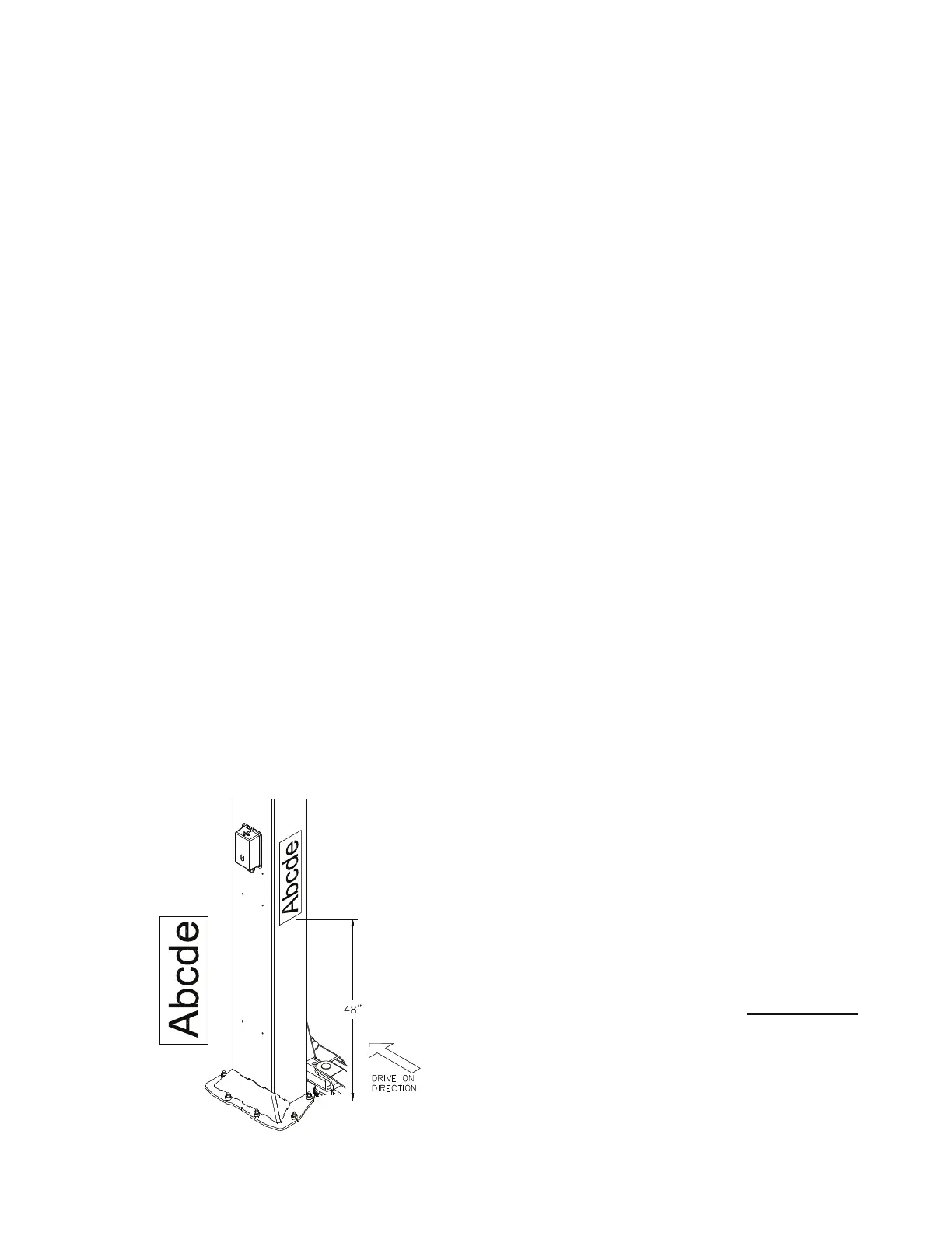
COLUMN DECAL PLACEMENT
38) Center decal on idler column, opposite of the
power unit.
39) Apply the decal 48” from the top of the base
plate, Fig 9.
Fig 9 – Decal Placement
FI
NAL ADJUSTMENTS
HYDRAULICS
40) Lower the lift to the floor and raise the lift
approximately one foot.
41) Start with Idler side first. Slowly and carefully
loosen the bleed plug on top side of the
cylinder just enough to allow the entrapped
air to escape. Repeat for power side.
42) Raise lift 6 inches. Repeat step 32 until no air
comes out of cylinder.
43) Pressure test hydraulic system. Energize
power unit, raise lift to full rise and continue
to run motor for additional 10 seconds.
(NOTE: pressure relief will make a high pitch
squeal sound for these 10 seconds.) Check
hydraulic system for leaks.
44) Energize power unit again for 10 seconds.
With a clean rag, wipe down both cylinder
rods. (The cylinders are shipped with a small
amount of clear anti-corosive lubricant tha
t
will be forced out through the wiper when the
lift reaches full rise.) If lubricant is not
wiped clean from the cylinder rod, the
cylinder will apear to be leaking.
S
YNCHRONIZING CABLES
45) Raise lift and insure carriages lower into
same lock position.
46) Adjust synchronizing cables so the tension is
equal in both cables and carriages are firmly
sitting on locks.
47) Cycle lift to insure that latches operate
simultaneously.
LOCK RELEASE CABLE
48) Raise lift to a lock position but don’t set into
the lock. Pull and release Power Column
lock release handle while watching Idler
Column lock. Adjust Cable tension by
removing slack and retightening cable clamp
at the power side.
IMPORTANT: IF IDLER SIDE
LOCK PAWL DOES NOT FULLY DISENGAGE, DAMAGE
MAY RESULT TO IDLER SIDE CARRIAGE AND OR CABLE
SYNCHRONIZING SYSTEM.
49) Tighten and trim wire ties.
5
0) Remove lock release knob and install both
covers. Replace lock release knob.
OWNER/OPERATOR CHECKLIST
51) Demonstrate the operation of the lift to the
owner/operator and review correct and safe
lifting procedures using the Lifting It Right
booklet as a guide.
52) Complete the Installation Checklist/Warranty
Validation questionnaire with the owner.
Review the terms of the warranty registration
card, and return the card and a copy of the
questionnaires to:
 Loading...