SL-12
Installation, Operation and Maintenance
Page 6
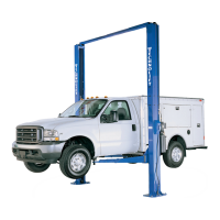
Fig 5 – Power Unit Mounting
19) Mount Power Unit to power column as shown
i
n Fig 5. The mounting hardware, (4) M8 hex
nuts, are pre-installed on power unit
mounting bracket.
20) Attach Hydraulic elbow fitting threading the
O-Ring end into the power unit.
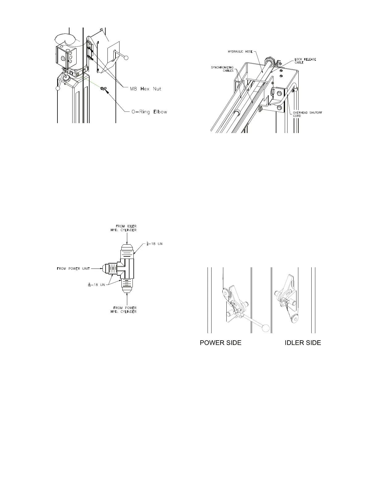
21) The hydraulic hose from the idler cylinder to
the tee fitting are slightly larger and have a
different size fitting. Note during installation
to attach the hoses in the correct end of the
tee. Fig 6.
Fig 6 – Hyd. Tee Fitting
22) IMPORTANT – To insure proper hose
fitting seal without damage to the fitting
follow this procedure for each hose
connection: Screw flared fitting on finger
tight. Rotate flared fitting 1 ½ flats or 90
degrees. Back the flared fitting off one full
turn and repeat.
23) Thread power unit hose (short) to elbow in
power on power unit.
24) Note: If lift is set to the tallest column height
an 18½” extension hose must be used at the
base of the Idler hydraulic cylinder.
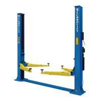
Beginning on the idler side start with the Idler
Column Hose (long) up the backside of the
column through the two capture rings and
guide at the top of the extension. Continue
across the overhead through each of the
guides as shown and down the backside of
the power column. See Fig 7.
Fig 7 – Hose Routing (Power Side)
25) Route the remaining Power column hose
beginning at the elbow fitting at the base up
the backside of the column. Join the three
hoses with the supplied union tee.
26) BE CERTAIN ALL F
ITTINGS AND CONNECTIONS
ARE TIGHT. IT IS THE INSTALLERS
RESPONSIBILITY TO INSURE SYSTEM IS LEAK-
FREE. Fill the Power Unit with three gallons of
clean 10wt anti-foam anti-rust hydraulic oil or
Dexron III ATF. DO NOT USE OILS WITH
DETERGENTS.
LOCK RELEASE
27) Install Lock Release Stud and Knob to the
Powre Column Lock using one M10 Nut.
28) Attach Mechanical Lock Release Cable
Assembly to each lock pawl. See Fig 8.
Fig 8 – Lock Assembly
T
HE LOCK RELEASE CABLE ADJUSTMENT IS NOT
COMPLETE UNTIL THE LIFT HAS BEEN LOWERED AND
“FINAL ADJUSTMENTS” HAVE BEEN MADE.
ARM INSTALLATION
29) Lubricate the arm pin or carriage arm pin
hole with “anti-seize” and install the arms.
Insure that the arm restraint gears engage
and disengage properly. Arm restraints
should disengage when lift is fully lowered. If
any binding occurs, insure that the large gear
mounted to the arm has been factory
installed tight against the arm pin.
 Loading...