EasyManua.ls Logo

technoswitch ORYX200 Series - User Manual

technoswitch ORYX200 Series
49 pages
Print Icon
To Next Page IconTo Next Page
Loading...
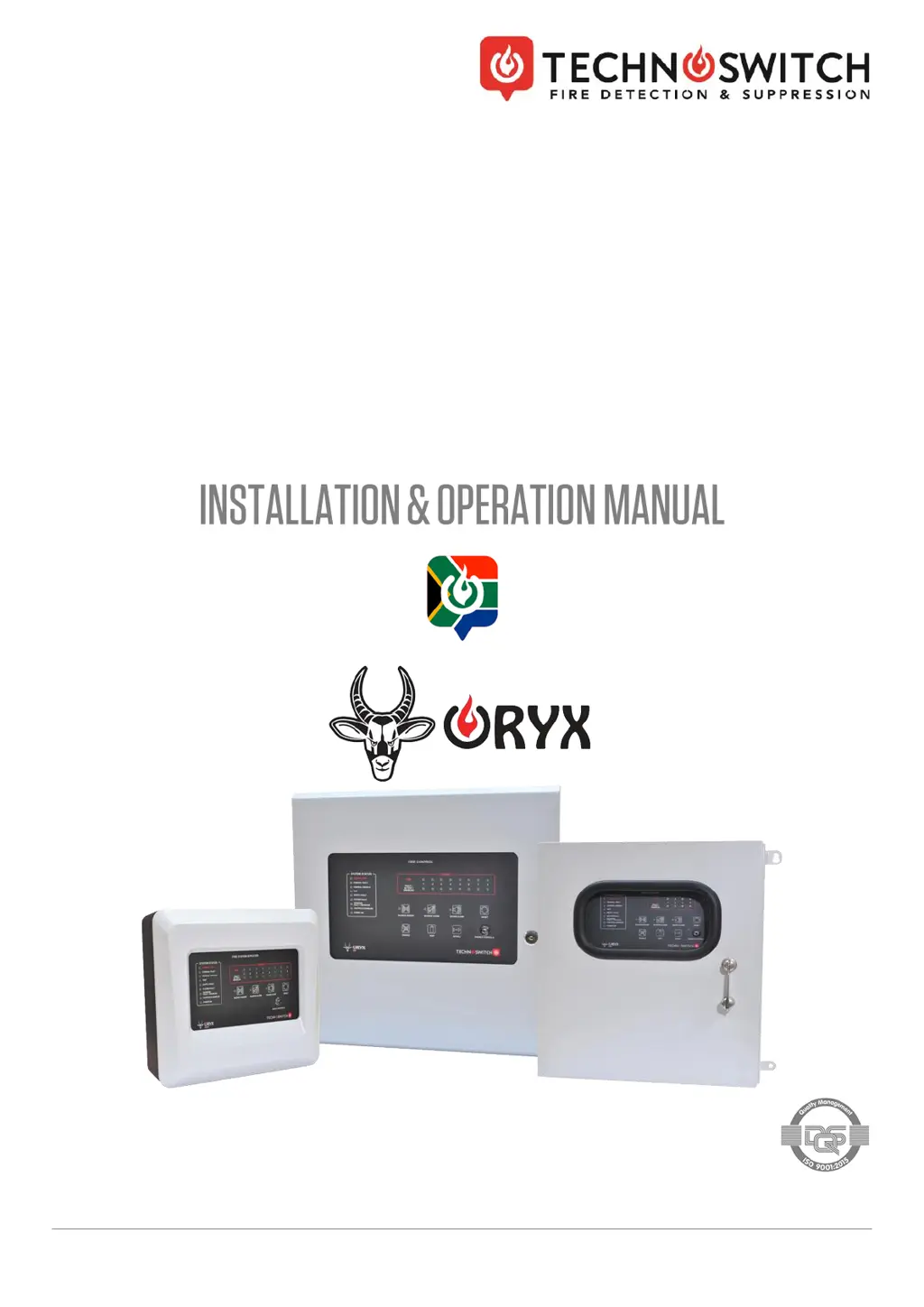
PRMAN-0047 ORYX200 S21 Fire Panel Range Rev 02.00 220224.docx E&OE
ORYX200 RANGE
Technoswitch Conventional
Fire Control Panels
ABS, Standard & Weatherproof Versions
Rev 02.00

Questions and Answers

  • M
    maryhooverAug 21, 2025
    What to do if my technoswitch Control Panel shows an A C Fault?
    • K
      Karen MullinsAug 21, 2025
      An A C Fault on your technoswitch Control Panel can occur due to several reasons: * Insufficient AC input: Check the mains supply or the termination to the PSU AC input. * Damaged input fuse or MOVs: Replace the fuse and investigate for an unstable mains supply. * AC input exceeding rating: Check the mains supply.
  • D
    Daniel SmithSep 3, 2025
    What does Low Earth Fault mean on my technoswitch ORYX200 Control Panel?
    • L
      Lindsey ChavezSep 3, 2025
      A Low Earth Fault on your technoswitch Control Panel indicates a short between DC negative and AC Earth. Remove the short. To determine the Earth voltage level, measure the DC voltage between any DC negative terminal and the AC earth.
  • J
    Jennifer BuchananSep 1, 2025
    What does High Earth fault mean on my technoswitch Control Panel?
    • A
      Anthony HernandezSep 1, 2025
      A High Earth fault on your technoswitch Control Panel indicates a positive DC voltage induction onto AC Earth. Remove the induction. To determine the Earth voltage level, measure the DC voltage between any DC positive terminal and the AC earth.
  • C
    codywilkinsAug 31, 2025
    What causes an AUX 24 V DC Fault on a technoswitch ORYX200 Control Panel?
    • C
      Craig BowenAug 31, 2025
      An AUX 24 V DC Fault on your technoswitch Control Panel is caused when the load exceeds the maximum current rating of 500 mA. Remove the load, check for short circuits, and consult the load's technical information.
  • M
    Michael HernandezAug 29, 2025
    What does it mean when there are no sounders or relays activating on my technoswitch ORYX200 Control Panel?
    • M
      Miguel GreenAug 29, 2025
      If no sounders or relays are activating, and the General Disable and Sounder Disable LEDs are ON while the Controls enabled LED is flashing on your technoswitch Control Panel, the service/commissioning mode is likely active. Ensure the service switch is in the left position.
  • F
    Felicia GomezAug 27, 2025
    What to do if my technoswitch ORYX200 shows a Charger Fail?
    • M
      Melissa ThomasAug 28, 2025
      If your technoswitch Control Panel displays a Charger Fail, it could be due to several reasons: * Unplugged batteries. * PSU in boost mode. * PSU in overload mode. * Circuit failure. Check the battery circuit connections or reduce the current draw on the panel to below 1.2 Amp.
  • B
    Bryan CaseAug 27, 2025
    What does it mean if the System Fault LED is flashing on my technoswitch ORYX200?
    • E
      Emily CurtisAug 27, 2025
      If the System Fault LED is flashing on your technoswitch Control Panel, the CPU may be frozen, or the panel may be in boot load mode. Ensure that the boot load jumper is not fitted, and then hard reset the power supply.
  • D
    Dr. Michael HendersonAug 25, 2025
    Why won't the sounders silence or the technoswitch Control Panel reset?
    • G
      gbrownAug 25, 2025
      If you cannot silence the sounders or reset the technoswitch Control Panel, ensure that the controls are enabled, as they may be disabled.
  • B
    Breanna ReyesAug 23, 2025
    What to do if my technoswitch ORYX200 indicates a Battery Fault?
    • A
      Ashley MccarthyAug 23, 2025
      If your technoswitch Control Panel shows a Battery Fault, it could be due to unplugged batteries or high internal resistance. Check the battery circuit connections or replace the batteries to resolve this.

Summary

Specifications

Product Specifications Overview

Covers part numbers, enclosure, dimensions, and environmental details.

Electrical & Power Specifications

Details mains supply, loads, PSU, and battery specifications.

Circuit & Interface Specifications

Zone, relay, input, L-Bus, and sounder circuit specifications.

Introduction

Standards and Compliance

Lists compliance standards for the ORYX range.

Safety Precautions

Important safety precautions before installation and operation.

Supporting Documentation

List of related documents available for download.

EN54 Functions

Details EN54 compliance and optional functions.

Installation Approvals

Fire System Installations

Requirements for fire system installation approvals.

Wiring Regulations

Adherence to wiring codes and regulations.

Identification of Parts

Installing the Enclosure

Wiring Installation

Recommended Cable Routing

Guidelines for routing low voltage and AC mains wiring.

Weatherproof Panel Termination Options

Cable routing for weatherproof panels with or without DIN rail.

AC Mains Wiring

Procedures for connecting the high-voltage AC mains supply safely.

Battery Positioning & Wiring

PSU Configuration

PSU LED Indications

Explains the meaning of LEDs on the power supply PCB.

PSU Fault Indications

Describes fault conditions and their associated indicators.

PSU Information Indications

Details load test and CPU running status indications.

Fault Relays;Outputs

Explains the function of fault relays and the 26V DC supply fault output.

Hard Reset Function

External Wiring

Sounder;Monitored Output Circuits

Details wiring for sounder and monitored output circuits with EOL resistors.

Detection Zone Inputs

How to wire and monitor detection zone inputs.

Relay Outputs

Specifications and types of relay outputs available.

Input Circuits

Details wiring for pre-programmed input circuits.

Aux DC Supply Output

Specifications for the 24V DC auxiliary output.

L-Bus Wiring

How to connect repeater panels to the L-Bus.

USB Connection for SOLAR

Connecting the panel to a PC for programming via USB.

Panel Loading

Battery Standby Calculation

Operation

Access Levels

Describes the three access levels for panel operation.

Front Panel Controls and Indications

Details the buttons, LEDs, and indicators on the front panel.

Enable Controls

How to enable panel controls using the key switch.

Re-sounding of Sounders (Evacuation)

Procedure to resound alarm sounders for evacuation.

Enabling;Disabling of Zones

How to enable or disable specific zones on the panel.

Enabling;Disabling of Sounder Circuits

How to enable or disable sounder circuits.

Enabling;Disabling of Programmable Input Circuits

Refers to SOLAR guide for programming input circuits.

One-Man Walk Test Mode

Procedure for putting zones into test mode for single-person testing.

Advanced Controls and Indications

Details service switch and boot loader jumper functions.

Programmable Features and Menu Structure

Programmable Features

Overview of configurable features using SOLAR software.

LCD Emulation Menu Structure (When Using SOLAR)

Details the panel's menu structure as displayed in emulation.

Service and Maintenance

Replacement of Components

Information on replacing components, focusing on batteries.

Batteries

Details battery lifespan, replacement schedule, and handling.

Appendix 1 - Troubleshooting

Troubleshooting Guide

Tables detailing common faults, causes, and required actions.

General Faults

Troubleshooting steps for general system faults.

Power Supply Faults

Troubleshooting steps for power supply related issues.

Short Circuit

Troubleshooting guide for short circuit faults on various circuits.

Low Resistance Fault

Troubleshooting guide for low resistance faults on various circuits.

Incorrect EOL Resistor

Troubleshooting guide for faults due to incorrect EOL resistors.

High Resistance Fault

Troubleshooting guide for high resistance faults on various circuits.

False Fire Alarms and Activations

Troubleshooting guide for false alarms and unexpected activations.

Normal Operating Range

Defines the normal operating resistance and voltage ranges.

Warranty

Disclaimer

Revision Information

technoswitch ORYX200 Series Specifications

General IconGeneral
CategoryControl Panel
Vibration Resistance10-55Hz, 1.5mm amplitude
Contact ConfigurationSPDT
Mechanical Life10, 000, 000 operations
Electrical Life100, 000 operations
Insulation Resistance≥100MΩ
Dielectric Strength500V AC for 1 minute
EnclosurePlastic
SeriesORYX200 Series
Supply Voltage12VDC or 24VDC (Nominal)

Related product manuals