TD20 Series VFD Function Parameters
-72-
Detailed instruction of parameters
P10 Group Simple PLC and multi-step speed control
0: Stop after running once. The VFD has to be
commanded again after finishing a cycle.
1: Run at the final value after running once. After finish a
signal, the VFD will keep the running frequency and
direction of the last run.
2: Cycle running. The VFD will keep on running until
receiving a stop command and then, the system will
stop.
Simple PLC
memory
selection
0: Power loss without memory
1: Power loss memory; PLC record the running stage
and frequency when power loss.
100.0% of the frequency setting corresponds to the Max.
Frequency P00.03.
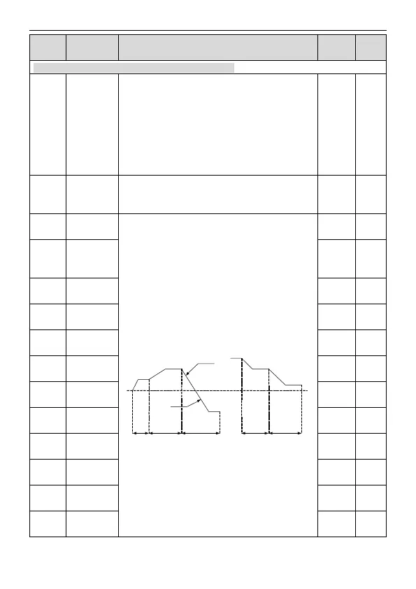
When selecting simple PLC running, set P10.02–P10.33
to define the running frequency and direction of all
stages.
Note: The symbol of multi-step determines the running
direction of simple PLC. The negative value means
reverse rotation.
P10.02
P10.04
P10.06
P10.32
P10.30
P10.28DEC time
(2 stages)
ACC time
(2 stags)
P10.03 P10.05 P10.07 P10.31 P10.33
multi-step speeds are in the range of --f
max
–f
max
and it
can be
TD20 series VFDs can set 16 stages speed, selected by
the combination of multi-step terminals 1–4,
corresponding to the speed 0 to speed 15.
The running
time of stage
0
The running
time of stage 1
The running
time of stage 2
The running
time of stage 3
The running
time of stage 4
The running
time of stage 5