Topdrive350 Series
Quick Startup Guide
2
• Always disconnect the main power supply
before touching any electrical component
associated to the inverter. Several
components can remain charged with high
voltages or remain in movement (fans)
even after the AC power is disconnected
or switched off.
• Wait at least five minutes after turning off
the input power for the complete discharge
of the power capacitors.
• Always connect the grounding point of the
inverter to the protection earth (PE).
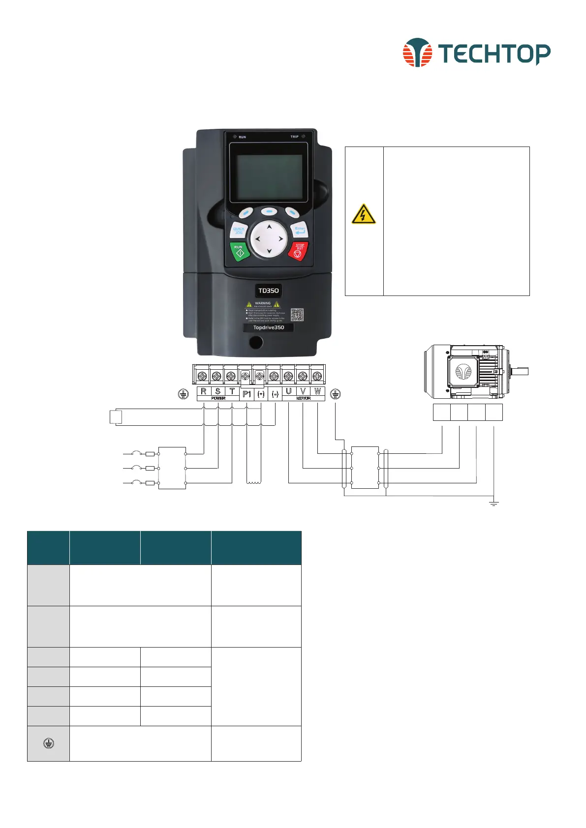
POWER CONNECTIONS
Verify the following wiring setup before you turn on the VFD
for the first time:
• Make sure the line voltage (L1/L2/L3) is NOT connected
to the output terminals (U/V/W) of the VFD.
• Ensure the motor is connected to the drive before apply-
ing power to the VFD.
The fuse, braking resistor, input reactor, input filter, out-
put reactor, output filter are optional parts. Please refer to
Peripheral Optional Parts of TD350 user manual for detailed
information.
Remove the yellow warning labels of PB, (+) and (-) on the
terminals before connecting the braking resistor; otherwise,
poor connection may occur.
Terminal
220V ≤20HP
460V ≤40HP
220V≥25HP
460V ≥50HP
575V≥25HP
Function
R, S, T
(L1, L2, L3)
Power input of the main circuit
Three phase AC input
terminals which are generally
connected with the power
supply.
U, V, W Power output of the VFD
Three phase AC output
terminals which are generally
connected to the motor.
P1 N/A
DC Reactor
Terminal 1
• P1 and (+) are connected
with the terminals of DC
reactor.
• (+) and (–) are connected
with the terminals of brake
unit.
• PB and (+) are connected
with the terminals of brake
resistor.
(+)
Brake Resistor
Terminal 1
DC reactor terminal 2,
Brake unit terminal 1
(–) N/A
Brake unit
terminal 2
PB
Brake Resistor
Terminal 2
N/A
PE
Protective grounding terminals, every machine
is provided 2 PE terminals as the standard
configuration. These terminals should be
grounded with proper techniques.
Protective grounding terminal
Three-phase
Supply
50/60Hz
Input
reactor
Input
filter
Fuse
(+)
(-)
Braking Unit
(optional)
L1
L2
L3
Output
reactor
Output
filter
T3 T2 T1 PE
DC-
DC+
(+)(P1)
DC Reactor
(Optional)
Three-phase
Supply
50/60Hz
Input
reactor
Input
filter
Fuse
(+)
(-)
Braking Unit
(optional)
L1
L2
L3
Output
reactor
Output
filter
T3 T2 T1 PE
DC-
DC+
(+)(P1)
DC Reactor
(Optional)
Three-phase
Supply
50/60Hz
Input
reactor
Input
filter
Fuse
(+)
(-)
Braking Unit
(optional)
L1
L2
L3
Output
reactor
Output
filter
T3 T2 T1 PE
DC-
DC+
(+)(P1)
DC Reactor
(Optional)
Note terminal location will vary depending on VFD rating. This power
connection diagram is based on 220V 18.5–30kW, 460V 37–55kW
and 575V 18.5–37kW TD350 VFDs. For further diagram instructions,
please refer to the TD350 User Manual pages 24-28.
TECHTOP HIGH-PERFORMANCE VECTOR DRIVES, TD350 QUICK STARTUP GUIDE
 Loading...


