Topdrive350 Series
Quick Startup Guide
5
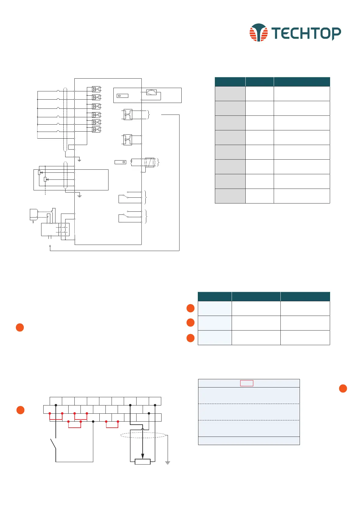
CONTROL CONNECTIONS
Multi-function input terminal 1
S4
S3
S2
S1
Multi-function input terminal 2
Multi-function input terminal 3
Multi-function input terminal 4
HDIA
High-speed pulse input or
Open collector input
HDIB
High-speed pulse input or
Open collector input
COM
PW
+24V
PE
+10V
Power used for
frequency setting
AI1
Multi-function
analog input
AI2
GND
PE
Safety
Input
Safety
swith
-10V
(external)
H1
H2
S1
S2
Open circuit
Safety
controller
+24V
Safety state
feedback
SW2
AO1
GNDV I
Analog output
0-10V/0-20mA
Optional between high-
speed pulse output and
open collector output
Y1
CME
Y1
Output
HDO
COM
RS485
communication
SW3
ON OFF
485+
485-
485G
Relay 1
output
Relay 2
output
RO1A
RO1B
RO1C
RO2A
RO2B
RO2C
REMOTE 2-WIRE START/STOP SETUP, WITH
SPEED POTENTIOMETER
Default Setting: The TD350 by default uses the keypad com-
mand to run and stop, follow instructions below to change to a
remote 2-wire start/stop with 0-10V speed reference.
Instructions to change to remote run/stop:
• Power down the drive, wait 5 min.
• Remove the protective covers (See TD350 User Manual) and
make the connections as shown below (see step 2).
• Verify that all connections are secure, replace covers
and power-up the drive.
• Follow the parameter settings in right hand table (see steps
3-5).
S1 S2 S3 S4 HDIA AI1 AI2 +10V
COM Y1 AO1 GND
HDIB
H2 +24V COM 485+PE 485-
H1 +24V +24V PW HDO
CME 485G
COM
Potentiometer
SPEED CONTROL
Switch
START/STOP
Jumper Jumper
*Parameter Default Change To
P00.01
0: Keypad (local) running
command channel
1: Terminal running
command channel
P00.06
0: Keypad, A frequency
command
1: AI1, A frequency
command
P05.01
1: S1 set to forward
rotation operation
--
01: TD350
16:02:35
Forward
Trml Ready
Set frequency
P17.00 Hz
DC bus voltage
P17.11 V
AboutMonitoring
Menu
Digital input terminal state
P17.12
60.00
648.0
0x0000
When P00.01=1
Local indicator will
change to Trml for
remote operation.
3
4
5
3
*To quickly access the function codes from the homepage, select:
Menu > Parameter setting > Func code quick setting
1
2
Terminals Quantity Description
Digital input 4 (S1-S4)
1kHz, NPN and PNP
(default NPN)
High speed
pulse input
2 (HDIA-HDIB)
50kHz, NPN and PNP
(default NPN)
Analog input 2 (AI1-AI2)
0~10V, 0~20mA,
-10V~+10V
ON-OFF output 1 (Y1)
Maximum output
frequency: 1kHz
High speed
pulse output
1 (HDO)
Maximum output
frequency: 50kHz
Analog output 1 (AO1) 0~10V, 0~20mA
Relay output 2 (RO1-RO2)
3A/250VAC,
1A/30VDC, NO+NC
Safe Torque Off
(STO)
2 (H1-H2)
Integrates safety
function-STO, SIL2
TECHTOP HIGH-PERFORMANCE VECTOR DRIVES, TD350 QUICK STARTUP GUIDE

 Loading...

