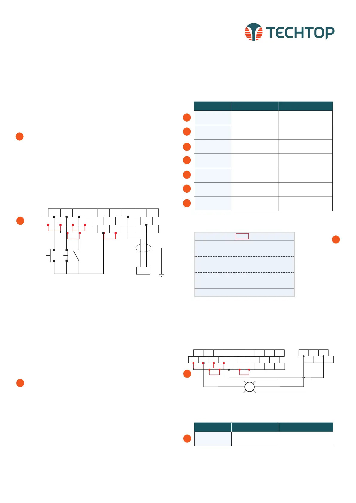
REMOTE 3-WIRE START/STOP SETUP, WITH
4-20mA REFERENCE
Default Setting: The TD350 by default uses the keypad com-
mand to run and stop, follow instructions below to change to a
remote 3-wire start/stop with 4-20mA speed reference.
Instructions to change to remote run/stop:
• Power down the drive, wait 5 min.
• Remove the protective covers (See TD350 User Manual) and
make the connections as shown below (see step 2).
• Verify that all connections are secure, replace covers
and power-up the drive.
• Follow the parameter settings in right hand table (see steps
3-9).
When P00.01=1
Local indicator will
change to Trml for
remote operation.
3
*Parameter Default Change To
P00.01
0: Keypad running
command channel
1: Terminal running command
channel
P00.06
0: Keypad, A frequency
command
1: AI1, A frequency command
P05.50 0: Voltage type 1: Current type
P05.01
1: S1 set to forward
rotation operation
--
P05.02
4: S2 set to forward
Jogging
3: S2 set to 3-wire control
operation
P05.03 7: S3 set to fault reset
2: S3 set to reverse rotation
operation
P05.11 0: 2-wire contol 1 2: 3-wire contol 1
3
4
5
6
7
8
9
CONNECTING A 24VDC PILOT LIGHT TO OUTPUT
RELAYS
Default Setting: The TD350 by default switches RO1 relay
contact when drive is in the run operation command. A terminal
is normally open, B is normally closed and C is common.
Instructions to change to remote run/stop:
• Power down the drive, wait 5 min.
• Remove the protective covers (See TD350 User Manual) and
make the connections as shown (see step 2).
• Verify that all connections are secure, replace covers
and power-up the drive.
• Follow the parameter settings in right hand table (see step
3).
RO1A RO1B RO1C
RO2A RO2B RO2C
24VDC Pilot Light
START/STOP INDICATOR
S1 S2 S3 S4 HDIA AI1 AI2 +10V
COM Y1 AO1 GND
HDIB
H2 +24V COM 485+PE 485-
H1 +24V +24V PW HDO
CME 485G
COM
Jumper Jumper
*Parameter Default Change To
P06.03 1: In operation --
3
1
2
1
2
Topdrive350 Series
Quick Startup Guide
6
S1 S2 S3 S4 HDIA AI1 AI2 +10V
COM Y1 AO1 GND
HDIB
H2 +24V COM 485+PE 485-
H1 +24V+24V PW HDO
CME 485G
COM
Jumper Jumper
N.O. SB1
START
N.C. SB2
STOP
Switch
REVERSE
4 to 20 mA
Reference
+
_
TECHTOP HIGH-PERFORMANCE VECTOR DRIVES, TD350 QUICK STARTUP GUIDE
01: TD350
16:02:35
Forward
Trml Ready
Set frequency
P17.00 Hz
DC bus voltage
P17.11 V
AboutMonitoring
Menu
Digital input terminal state
P17.12
60.00
648.0
0x0000
*To quickly access the function codes from the homepage, select:
Menu > Parameter setting > Func code quick setting
*To quickly access the function codes from the homepage, select:
Menu > Parameter setting > Func code quick setting
 Loading...


