EXPLORER II - Outdoor Microwave Barrier
Outdoor Microwave Barrier - EXPLORER II
4
Fig. 5
C
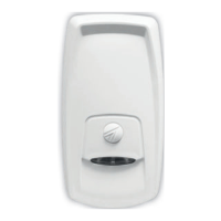
2.5 PROTECTION OF PERIMETERS SUPERIOR TO THE
DETECTIONRANGE (180 METERS)
If the perimeter to be protected is superior to the maximum detection
range of the barrier (max. 180m), a series of barriers have to be
positioned side by side (fig. 5).
The distance between the aligned barriers should not exceed 50cm in
order to avoid undetected intrusion via corridor "C".
A transmitter must never be installed next to a reveiver but next to another
transmitter in order to prevent from possible interferences.
The distance A (RX1 to RX2 or TX3 to TX2) has to be the following:
+ type 0600: distance A = 6m
+ type 1200: distance A = 8m
+ type 1800: distance A = 10m
3. ALIGNMENT
3.1 ALIGNMENT BY DIGITAL VOLTMETER
After having positioned the barrier by observing prior instructions, make an
initial visual alignment. Insert the jumper J2 to exclude the automatic gain
control (fig. 7).
The green LED is
switched on and signals
the reception of the signal
emitted by the transmitter.
Should the LED not be
switched on, check the
position of the frequency
switches. Mesure the
tension on point A and B
on the test connector (fig.
8) with the help of a digital
voltmeter set in AC. If
tension is inferior or equal
to 1.5V the barrier has not
been aligned properly or there are too many obstacle in the way. In this case,
it is recomended to change the position of the transmitterin the first place,
if the result should not be satisfactory try to move also the receiver.
Fig. 6
The transmitter
9
9. TEST
9.1 ELECTRONIC BOARD TEST
EXPLORER II is equipped with a test section which controls the correct
functioning of the electronic board. The stand-by input of the receiver board
has to be connected to the negative stand-by terminal of the control panel.
If the stand-by input is not connected, the test function is disabled. If the
control panel is in stand-by, negative voltage is present on the stand-by input
of the receiver board. If the control panel is armed, negative voltage is missing
on the stand-by input.
On the receiver board there are a stand-by input, two fault terminals which
correspond to the contacts of a normally closed relay (open = fault) and two
alarm terminals which correspond to the contacts of another normally closed
relay (open = alarm).
If there is negative voltage on the stand-by input of the receiver board, the
barrier passes into test condition:
> Board well functioning:
» Fault output contact closed
» Alarm output contact open
> Board faulty:
» Fault output contact open
 Loading...