EXPLORER II - Outdoor Microwave Barrier
Outdoor Microwave Barrier - EXPLORER II
5
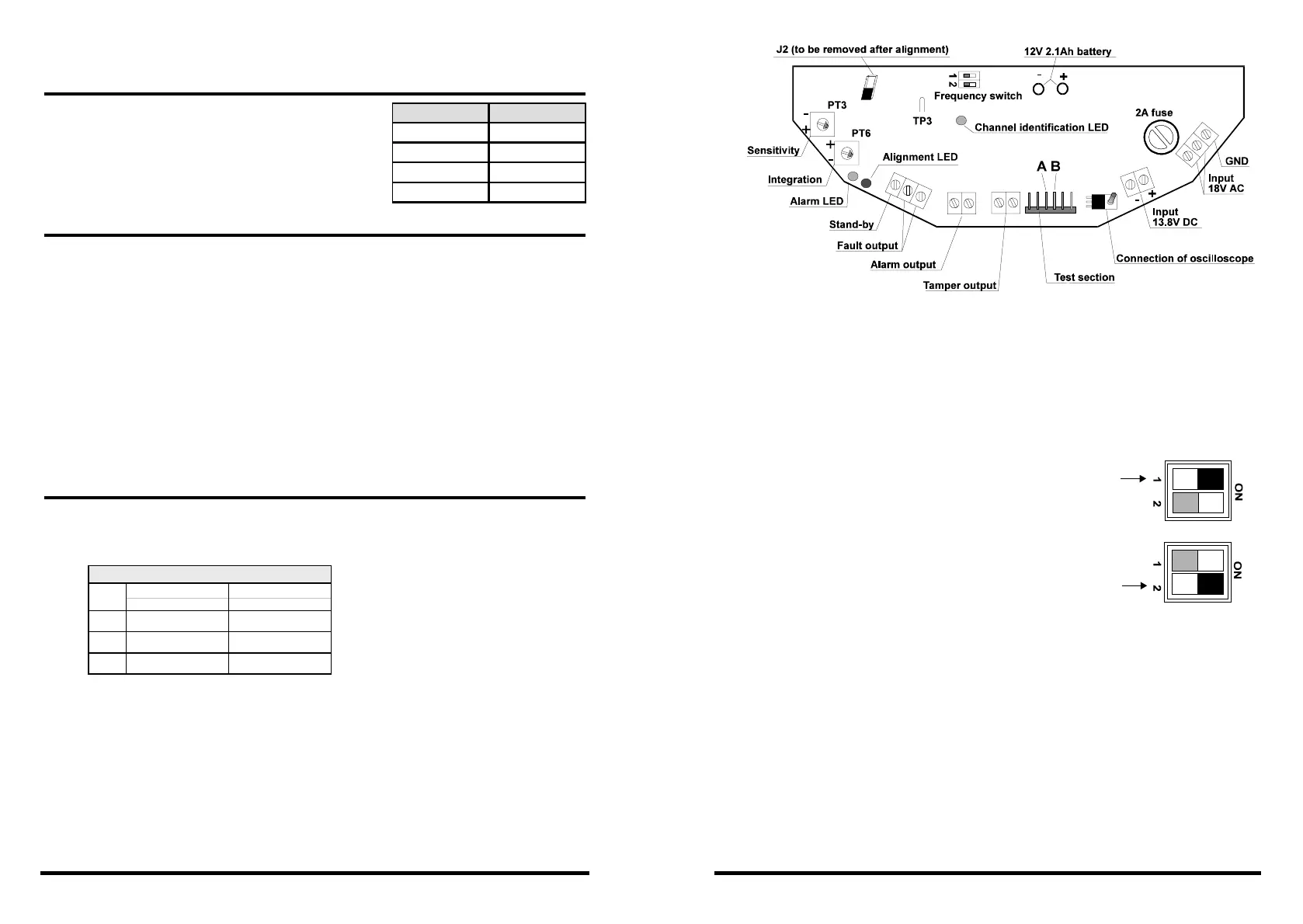
Fig. 7
The receiver
Tension has to be superior to 1.5V (max. 3V AC). The procedure has to be
repeated after fixing of all the screws which have been loosened for alignment.
3.2 ALIGNMENT BY CATHODE-RAY OSCILLOSCOPE
Connect the probe of the cathode-ray oscilloscope to test point TP3 (fig. 8).
Adjust the time base of the cathode-ray
oscilloscope according to the modulation channel
used:
+ Channel 1 = 50µs/division (fig.8)
+ Channel 2 = 20µs/division (fig.9)
Position the switch V/div on 1V AC. A modulated
voltage appears with a period of:
+ Channel 1 = 180 µs
+ Channel 2 = 127 µs
The minimum amplitude accepted is 2.5Vpp, the
maximum signal of saturation is 4Vpp.
Search for the maximum amplitude on the cathode-ray oscilloscope. The
trace of the obtained signal has to be clear and without overmodulations.
If this is not the case, look for possible reasons (e.g. interferences with
another barrier, high power radio transmissions, large metallic carrier pipes
that may run underground, high voltage electric carrier pipes near by etc.)
In case the source of perturbation is a powerful field of radio frequency, it
is advisable to mount the barriers at 50cm height from the ground.
Fig. 8
Fig. 9
8
6. COMPATIBILITY WITH PREVIOUS VERSIONS
OF EXPLORER
Consider that replacing a barrier of the previous
version by the new one (EXPLORER II) the
transmission frequency has to be adjusted
according to the following table:
7. LED FUNCTIONS
There are three LED on the receiver board (fig. 7).
The red alarm LED signals the status of the alarm relay:
» LED off relay closed (no alarm)
» LED on relay open (alarm)
The yellow alignment LED indicates the intensity of the signal received:
» LED off good connection
» LED on insufficient signal power (the barrier has to be aligned)
The green channel identification LED indicates if TX and RX are set on
the same transmission frequency:
» LED off TX and RX set on different frequencies
» LED on TX and RX set on the same frequency.
8. MICROWAVE FIELDS
The microwave field diameter depends on the distance between TX and
RX. The field's shape can be modified by obstacles, such as metal walls
or tunnels.
a b
m
n. max. m
n. max.
60m 50 cm 120 cm 50 cm 150 cm
120m 100 cm 250 cm 100 cm 300 cm
180m 150 cm 300 cm 150 cm 400 cm
DETECTION DIAGRAM
TYPE
EXPLORER EXPLORER II
Channel 1 -
Channel 2 Channel 1
Channel 3 Channel 2
Channel 4
 Loading...