Do you have a question about the Tecnologic TLK 38 and is the answer not in the manual?
TLK 38 is a "single loop" digital microprocessor-based controller with multiple control modes and functions.
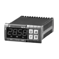
Details the functions of the keys and indicators on the front panel of the TLK 38 controller.
Procedure for rapidly programming the active Set Point and alarm thresholds.
Enables selection of control states and entry into parameter programming menus.
Describes how parameters are made accessible between 'OPEr' and 'ConF' menus.
Details the three possible control states: automatic (rEG), off (OFF), and manual (OPLO).
Explains how to pre-program and select one of up to four active Set Points.
Specifies the intended use of the instrument and safety precautions for installation.
Provides guidance on flush-in panel mounting, environmental considerations, and ventilation.
Details how to properly wire the instrument, including terminal connections and power supply checks.
Illustrates the wiring diagram for power supply, outputs, and various input signals.
Describes accepted input types and parameters for measuring and visualizing process data.
Details how to program the instrument's outputs for control or alarm functions.
Explains the parameters and operation of the ON/OFF control mode with hysteresis.
Details the Neutral Zone ON/OFF control, used for plants with positive/negative increase elements.
Describes the Single Action PID control, its parameters, and algorithm.
Explains the Double Action PID control for systems with heating and cooling elements.
Covers the Auto-Tuning and Self-Tuning functions for automatic PID parameter calculation.
Details how to program ramps and dwell times for gradual Set Point changes.
Explains the Soft-Start function to limit control power during initial operation.
Describes the configuration and behavior of alarm outputs AL1 and AL2.
Details error codes, their reasons, and recommended actions for troubleshooting.
Provides recommendations for cleaning the instrument safely.
Outlines the warranty period, conditions, and procedures for repairs.
Lists electrical specifications including power supply, consumption, and input/output types.
Provides details on the instrument's housing, dimensions, weight, and mounting.
Includes diagrams for panel cut-out and physical mounting of the instrument.
Summarizes the available control modes and display resolution options.
Explains the structure of the product ordering code for different configurations.
| Digital I/O | 2 digital inputs |
|---|---|
| Output | 0-20mA / 4-20mA / 0-5V / 0-10V |
| Control Mode | PID / On-Off |
| Power Supply | 24V AC/DC |
| Display | 4-digit red LED |
| Mounting | Panel |
| Ethernet | Not available |
| USB Ports | Not available |
| Serial Ports | RS485 |