Do you have a question about the Tecnologic TLK 48 and is the answer not in the manual?
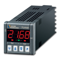
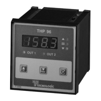
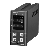
Overview of the microprocessor-based digital electronic controller.
Details front panel components and indicators.
Rapid programming of active Set Point and alarm thresholds.
How to select control states and program parameters.
How to make parameters visible in the OPER menu.
The three control states: automatic, OFF, and manual.
How to select one of up to four pre-programmed Set Points.
Specifies intended and safe usage conditions for the instrument.
Guides physical installation of the controller into a panel.
Details wiring procedures for power and signal connections.
Visual representation of the controller's electrical connections.
How the instrument displays measured values and output status.
How to configure the controller's output functions.
Parameters and operation of the ON/OFF control mode.
Neutral Zone ON/OFF control mode and its parameters.
Parameters and operation of Single Action PID control.
Parameters and operation of Double Action PID control.
Automatic tuning methods for PID controller parameters.
Ramp and dwell time functions for set point changes.
Soft-Start function for limiting control power at startup.
Configuration and management of alarm outputs.
Function detecting interruptions in the control loop.
Programmable functions assigned to the 'U' key.
Parameter configuration using the KEY01 device.
Error messages and troubleshooting actions.
Instructions for cleaning the instrument.
Warranty terms and repair procedures.
Electrical characteristics and power requirements.
Physical dimensions and material specifications.
Dimensions for panel mounting and installation.
Overall functional features and capabilities of the controller.
Available input ranges for different sensor types.
Coding system for ordering specific instrument configurations.
| Brand | Tecnologic |
|---|---|
| Model | TLK 48 |
| Category | Controller |
| Language | English |