4) Program an output as 2.rEG if the instrument controls a
dual-action plant
5) Program par. "SELF" = yES
6) Exit from the parameter programming.
7) Connect the instrument to the controlled plant.
8) Activate Self-tuning selecting par. “tunE” in the main menu (or
by correctly programming key “U”).
When the Self-tuning function is active, the led AT/ST is
permanently lit up and all the PID parameters ("Pb", "Int", "dEr",
etc.) are no longer visualized.
Note : It’s always preferable tuning the instrument using the
Autotuning and to activate the Selftuning after because the tuning
through Selftuning is more slow.
To stop the Auto-tuning cycle or deactivate the Self-tuning function
select one of the control types : "rEG", "OPLO" or "OFF" from the
menu “SEL”. If the instrument is switched off during Auto-tuning or
with the Self-tuning function activated, these functions will remain
activated the next time it is switched on.
4.8 - REACHING OF THE SET POINT AT CONTROLLED SPEED
AND AUTOMATIC SWITCHING BETWEEN TWO SET POINTS
(RAMPS AND DWELL TIME)
All the parameters referring to the ramps functioning are contained
in the group “
]
rEG”.
It is possible to reach the set point in a predetermined time (in any
case longer than the time the plant would naturally need). This
could be useful in those processes (heating or chemical
treatments, etc.) where the set point has to be reached gradually, in
a predetermined time.
Once the instrument has reached the first Set Point (SP1) it is pos-
sible to have automatic switching to the second Set Point (SP2) af-
ter a set time, thus obtaining a simple automatic process cycle.
These functions are available for all the programmable controls
(PID single and double action, ON/OFF and Neutral Zone
ON/OFF).
The function is determined by the following parameters :
"SLor" - Gradient of first ramp expressed in unit/minute
"SLoF" - Gradient of second ramp expressed in unit/minute.
"dur.t" - Dwell time of Set Point “SP1” before automatic switching
to Set Point “SP2” (expressed in hrs. and min.).
The functions are deactivated when the relative parameters are =
InF.
If is desired only one ramp (ex. to reach “SP1”) it is enough to
program on the par. "SLor" the desired value.
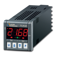
The ramp "SLor" it will always active at power on and when the
Active Set Point value is changed.
SP1
[Unit]
PV
SP1 Value
change
SP1
tim e [m in.]
SLor
SLor
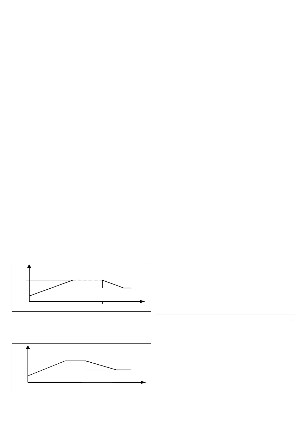
If it is desired an automatic cycle from the power on instead it is
necessary to program the par. "nSP" = 2, to program the two Set
Point values "SP1" and "SP2" and naturally to program the par.
"SLor", "dur.t" and "SLoF" with the desired values.
In this case at the end of the cycle all the ramps won't be more
active.
[U nit]
SP1
PV
AUTO
change
Set
dur.t
SP2
tim e [m in .]
SLor
SLoF
Examples with starts from values lower than SP and with
decreasing of SP.
Note: In case of PID control, if Auto-tuning is desired whilst the
ramp function is active, this will not be carried out until the tuning
cycle has been completed. It is therefore recommended that
Auto-tuning be started avoiding activating the ramp function and,
once the tuning is finished, deactivate Auto-tuning (“Auto” = OFF),
program the desired ramp and, if it automatic tuning is desired,
enable the Self-tuning function.
4.9 - SOFT-START FUNCTION
All the parameters referring to the Soft -Start functioning are
contained in the group “
]
rEG”.
The Soft-Start function only works through PID control and allows
the limitation of control power when the instrument is switched on,
for a programmable period of time.
This is useful when the actuator, driven by the instrument, may be
damaged excess power supplied when the application is not yet in
the normal rating. (ex. for certain heating elements).
The function depends on the following parameters :
“St.P” - Soft-Start power
“SSt” - Soft-Start time (expressed in hh.mm)
“HSEt” - End Soft Start cycle threshold
If both parameters are programmed with values other than OFF,
when switched on the instrument gives an output power as
programmed on par. “St.P” for the time programmed on par. “SSt”
or when is reached the absolute value programmed at par. “HSEt”.
Practically, the instrument works in manual condition and switches
to automatic control at the elapsing of time “SSt” or when is
reached the absolute value programmed at par. “HSEt”.
To disable the Soft-Start function simply program par. “SSt” = OFF.
Whenever, a measurement errors occurs during the Soft-Start
execution, the function is interrupted and the instrument gives an
output power as programmed on par. “OPE”.
If the measurement is restored, the Soft-Start is still deactivated.
If it’s desired to activate the Autotuning with Soft-Start set par.
“Auto”=4.
The Autotuning will start automatically at the end of programmed
Soft-Start cycle at the condition that the process value is lower (with
“Func” =HEAt) than [SP- |SP/5|] or higher (with “Func” =CooL) than
[SP+ |SP/5|].
4.10 - ALARMS OUTPUTS FUNCTIONS (AL1, AL2, AL3)
The alarms (AL1, AL2, AL3) are depending on the process value
and before to set his functioning it’s necessary to establish to which
output the alarm has to correspond to.
First of all it’s necessary to configure, in the parameters group
“
]
Out”, the parameters relative to the outputs required as alarm
(“O1F” , “O2F”, “O3F”) programming the parameter relative to the
desired output as follows :
= ALno if the alarm output has to be ON when the alarm is active,
while it’s OFF when the alarm is not active
= ALnc if the alarm output has to be ON when the alarm is not
active, while it’s OFF when the alarm is active
= ALni if the alarm output has to be ON when the alarm is not
active, while it is OFF when the alarm is active but with reverse led
indication (led ON= alarm OFF).
Note:
In all the examples that follow is made reference to the alarm
AL1. Naturally the operation of the other alarms results analogous.
Have now access at the group “
]
AL1”, and program on par.
“OAL1” , to which output the alarm signal has to be sent.
The alarm functioning is instead defined by parameters :
"AL1t " - ALARM TYPE
"Ab1" - ALARM CONFIGURATION
“AL1” - ALARM THRESHOLD
“AL1L” - LOW ALARM THRESHOLD (for band alarm) OR
MINIMUM SET OF AL1 ALARM THRESHOLD (for low or high
alarm)
“AL1H” - HIGH ALARM THRESHOLD (for band alarm) OR
MAXIMUM SET OF AL1 ALARM THRESHOLD (for low or high
alarm)
“HAL1” - ALARM HYSTERESIS
“AL1d” - ALARM ACTIVATION DELAY (in sec.)
TECNOLOGIC spa - TLK 48 - OPERATING INSTRUCTIONS - Vr. 03 - ISTR 06481 - PAG. 7
 Loading...