By using par. “InE” it is also possible to decide the conditions of
the input error, allowing the instrument to give the power
programmed on par. “OPE” as output.
The possibilities of par. “InE” are :
= Or : the condition occurs in case of over-range or probe breakage
= Ur : the condition occurs in case of under-range or probe
breakage
= Our : the condition occurs in case of over-range or under-range
or probe breakage
Using par. “diSP”, located in the group “
]
PAn”, it is possible to set
normal visualization of the display which can be the process
variable (dEF), the control power (Pou), the active Set Point (SP.F)
the Set Point operating when there are active ramps (SP.o) or
alarm threshold AL1, AL2 or AL3 (AL1, AL2, AL3).
Again in the group “
]
PAn” the par. “AdE” is present that defines
the 3 led shift index functioning.
The lighting up of the green led = indicates that the process value
is within the range [SP+AdE ... SP-AdE], the lighting up of the led –
indicates that the process value is lower than [SP-AdE] and the
lighting up of the led + indicates that the process value is higher
than [SP+AdE].
4.2 - OUTPUTS CONFIGURATION
The instrument’s outputs can be programmed by entering the group
of parameters “
]
Out, where the relative parameters “O1F”, “O2F”
and “O3F” (depending on the number of outputs available on the
instrument) are located.
The outputs can be set for the following functions :
- Main control output (1.rEG)
- Secondary control output (2.rEG)
- Alarm output normally open (ALno)
- Alarm output normally closed (ALnc)
- Alarm output normally closed with led reverse indication (ALni)
- Output deactivated (OFF)
The coupling outputs number outputs – number alarms can be
made in the group referring to the alarm to the alarm (“
]
AL1”, “
]
AL2”,
“
]
AL3”).
4.3 - ON/OFF CONTROL (1.rEG)
All the parameters referring to the ON/OFF control are contained in
the group “
]
rEG”.
This type of control can be obtained by programming par."Cont" =
On.FS or = On.FA and works on the output programmed as 1.rEG,
depending on the measure, on the active Set Point “SP”, on the
functioning mode "Func” and on the hysteresis "HSEt".
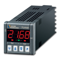
The instrument carries out an ON/OFF control with symmetric
hysteresis if “Cont" = On.FS or with asymmetrical hysteresis if
“Cont” = On.FA.
OUT
SP
PV
off
ON
HEAt - On.FA
OUT
time
HSEt
SP
PV
HSEt
time
C oo L - O n .FA
ON ON ON ON ON
off off off
CooL - On.FSHEAt - On.FS
ONON
OUT
SP
off
PV
off
ON
HSEt
time
OUT
ON
SP
PV
ON
off off
ON
time
HSEt
HSEt
HSEt
1.rEG 1.rEG
1.rEG1.rEG
The control works in the following way : in the case of reverse
action, or heating (“FunC”=HEAt), it deactivates the output, when
the process value reaches [SP + HSEt] in case of symmetrical
hysteresis, or [SP] in case of asymmetrical hysteresis and is then
activated again when the process value goes below value [SP -
HSEt].
Vice versa, in case of direct action or cooling ("Func”=CooL), it
deactivates the output, when the process value reaches [SP -
HSEt] in case of symmetrical hysteresis, or [SP] in case of
asymmetrical hysteresis and is activated again when the process
value goes above value [SP + HSEt].
4.4 - NEUTRAL ZONE ON/OFF CONTROL (1.rEG - 2.rEG)
All the parameters referring to Neutral Zone ON/OFF control are
contained in the group “
]
rEG”.
This type of control can be obtained when 2 outputs are
programmed respectively as 1.rEG and 2.rEG and the par. “Cont”
= nr .
The Neutral Zone control is used to control plants in which there is
an element which causes a positive increase (ex. Heater,
humidifier, etc.) and an element which causes a negative increase
(ex. Cooler, de-humidifier, etc).
The control functions works on the programmed outputs depending
on the measurement, on the active Set Point “SP” and on the
hysteresis "HSEt".
The control works in the following way : it deactivates the outputs
when the process value reaches the Set Point and it activates the
output 1.rEG when the process value goes below value [SP -
HSEt], or it activates the output 2.rEG when the process value goes
above [SP + HSEt].
Consequently, the element causing a positive increase has to be
connected to the output programmed as 1.rEG while the element
causing a negative increase has to be connected to the output
programmed as 2.rEG.
0N
OUT 2.rEG
(cooling)
OUT 1.rEG
(heating)
SP
PV
off
0N
off
off
off
0N
time
HSEt
HSEt
If 2.rEG output is used to control compressor is possible to use the
“Compressor Protection” function that has the meaning to avoid
compressor “short cycles”.
This function allows a control by time on the output 2.rEG
activation, independently by the temperature control request.
The protection is a “delayed after deactivation” type.
This protection permits to avoid the output activation for a time
programmable on par. “CPdt” (expressed in sec.); the output
activation will occurs only after the elapsing of time “CPdt”.
The time programmed on parameter “CPdt” is counted starting from
the last output deactivation.
Obviously, whether during the time delay caused by the
compressor protection function, the regulator request should stop,
the output activation foreseen after time “CPdt” would be erased.
The function is not active programming “CPdt” =OFF.
The led relative to 2.rEG output blinks during the phases of output
activation delay, caused by “Compressor Protection” function.
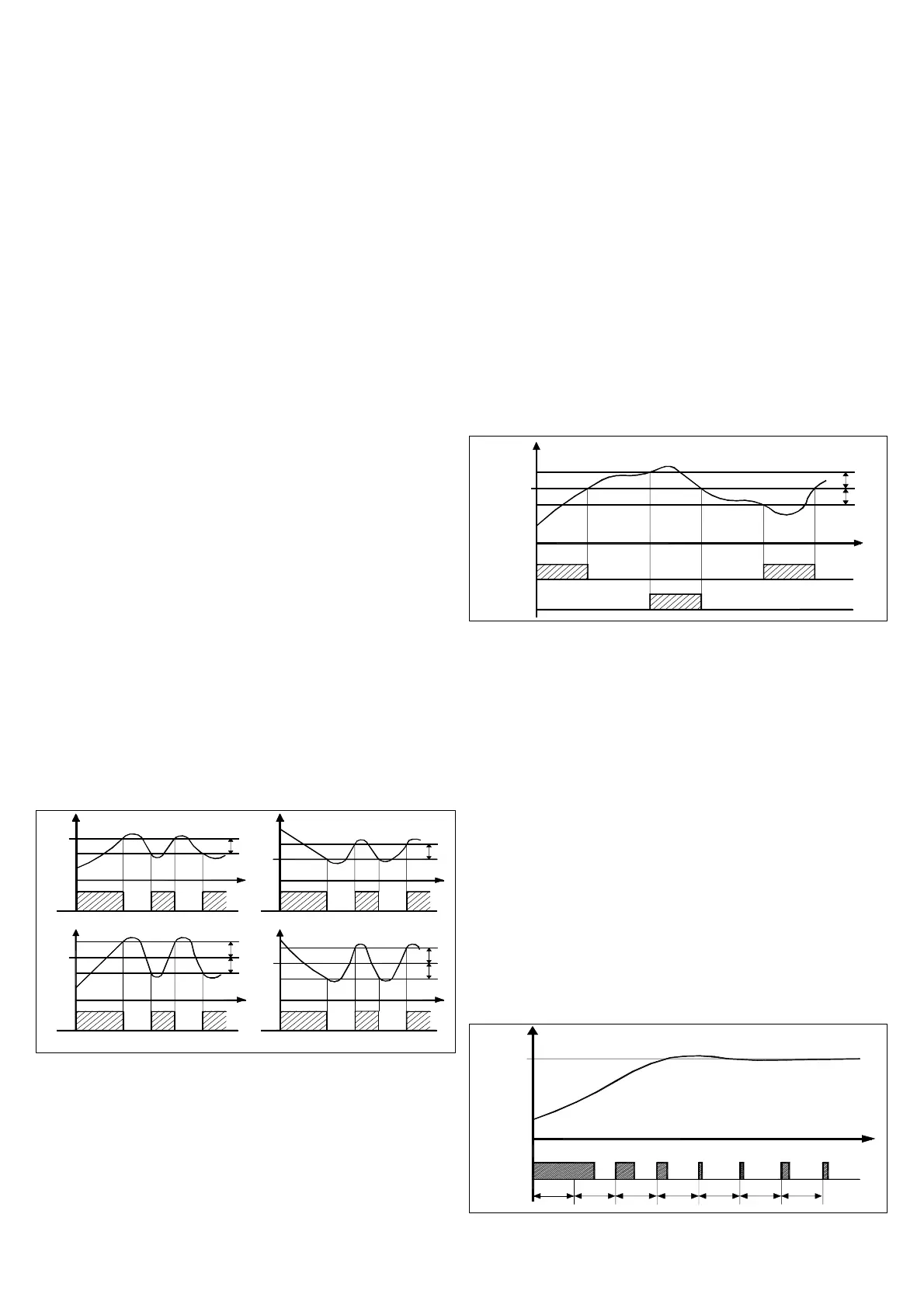
4.5 - SINGLE ACTION PID CONTROL (1.rEG)
All the parameters referring to PID control are contained in the
group “
]
rEG”.
The Single Action PID control can be obtained by programming
par."Cont" = Pid and works on the output 1.rEG depending on the
active Set Point “SP”, on the functioning mode "Func” and on the
instrument’s PID algorithm with two degree of freedom.
0N
tc r1
1.rEG
(H E a t)
SP
PV
tcr1
off
tcr1tcr1tcr1 tc r1
0N
off off
0N
offoff
0N 0N
tcr1
off
0N 0N
tim e
OUT
TECNOLOGIC spa - TLK 48 - OPERATING INSTRUCTIONS - Vr. 03 - ISTR 06481 - PAG. 5
 Loading...