The instrument can be removed from its housing from the front side
: it is recommended that the instrument be disconnected from the
power supply when it is necessary to carry out this operation.
3.3 - ELECTRICAL CONNECTION
Carry out the electrical wiring by connecting only one wire to each
terminal, according to the following diagram, checking that the
power supply is the same as that indicated on the instrument and
that the load current absorption is no higher than the maximum
electricity current permitted.
As the instrument is built-in equipment with permanent connection
inside housing, it is not equipped with either switches or internal
devices to protect against overload of current: the installation will
include an overload protection and a two-phase circuit-breaker,
placed as near as possible to the instrument, and located in a
position that can easily be reached by the user and marked as
instrument disconnecting device which interrupts the power supply
to the equipment.
It is also recommended that the supply of all the electrical circuits
connected to the instrument must be protect properly, using
devices (ex. fuses) proportionate to the circulating currents.
It is strongly recommended that cables with proper insulation,
according to the working voltages and temperatures, be used.
Furthermore, the input cable of the probe has to be kept separate
from line voltage wiring. If the input cable of the probe is screened,
it has to be connected to the ground with only one side.
We recommend that a check should be made that the parameters
are those desired and that the application functions correctly before
connecting the outputs to the actuators so as to avoid
malfunctioning that may cause irregularities in the plant that could
cause damage to people, things or animals.
Tecnologic S.p.A. and its legal representatives do not assume
any responsibility for any damage to people, things or animals
deriving from violation, wrong or improper use or in any case
not in compliance with the instrument’s features.
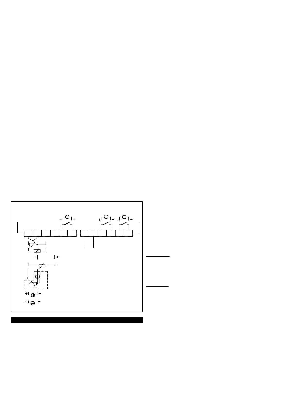
3.4 - ELECTRICAL WIRING DIAGRAM
SSR
RELAYS
NO
(Max 20 mA)
PTC
NTC
ext.
gen.
OUT 12 VDC
SUPPLY
0..50/60 mV
0/4..20 mA
0/1..5 V
0/2..10 V
ACTIVE
0..1 V
ACTIVE
PASSIVE
(2 wires)
4..20 mA
4..20 mA
4
Pt100
TLK 48
TC
INPUT
21 3 75 6 8
C
9 10
OUT2
NO
11
C
12
OUT1
Relay OUT3: 5A-AC1 (2A-AC3) 250VAC
SSR: 8 mA / 8 VDC
Relays OUT1,2: 8A-AC1 (3A-AC3) 250VAC
OUT3
C NO
4 - FUNCTIONS
4.1 - MEASURING AND VISUALIZATION
All the parameters referring measurements are contained in the
group “
]
InP”.
Depending on the model required the input accept:
C: Thermocouples temperature probes (J,K,S and TECNOLOGIC
IRS Infrared sensors), mV signals (0..50/60 mV, 12..60 mV),
Thermoresistances PT100.
E : Thermocouples temperature probes (J,K,S and TECNOLOGIC
IRS Infrared sensors), mV signals (0..50/60 mV, 12..60 mV),
Thermistors PTC and NTC.
I : normalized analogue signals 0/4..20 mA
V : normalized analogue signals 0..1 V, 0/1..5 V, 0/2..10 V
Depending on the model, using par. “SEnS”, it’s possible to select
the type of input probe, which can be :
- for thermocouples J (J), K (CrAL), S (S) or for infrared sensors
serie TECNOLOGIC IRTC1 with linearization J (Ir.J) or K (Ir.CA)
- for thermoresistances Pt100 IEC (Pt1) or thermistors PTC
KTY81-121 (Ptc) or NTC 103AT-2 (ntc)
- for normalised signals in current 0..20 mA (0.20) or 4..20 mA
(4.20)
- for normalised signals in tension 0..1 V (0.1), 0..5 V (0.5), 1..5 V
(1.5), 0..10 V (0.10) or 2..10 V (2.10).
- for normalised signals in tension 0..50 mV (0.50), 0..60 mV (0.60),
12..60 mV (12.60).
We recommend to switch on and off the instrument when these
parameters are modified, in order to obtain a correct measuring.
For the instruments with input for temperature probes (tc, rtd) it’s
possible to select, through par. “Unit”, the unit of measurement
(°C, °F) and, through par. “dP” (Pt100, PTC and NTC only) the
desired resolution (0=1°; 1=0,1°).
Instead, with regards to the instruments with normalised analogue
input signals, it is first necessary to program the desired resolution
on par. “dP” (0=1; 1=0,1; 2=0,01; 3=0,001) and then, on par.
"SSC", the value that the instrument must visualise at the
beginning of the scale (0/4 mA, 0/12 mV, 0/1 V o 0/2 V) and, on
par. "FSC", the value that the instrument must visualise at the end
of the scale (20 mA, 50 mV, 60 mV, 5 V or 10 V).
The instrument allows for measuring calibration, which may be
used to recalibrate the instrument according to application needs,
by using par. “OFSt” and “rot”.
Programming par. “rot”=1,000, in par. “OFSt” it is possible to set a
positive or negative offset that is simply added to the value read by
the probe before visualisation, which remains constant for all the
measurements.
If instead, it is desired that the offset set should not be constant for
all the measurements, it is possible to operate the calibration on
any two points.
In this case, in order to decide which values to program on par.
“OFSt” and “rot”, the following formulae must be applied :
“rot” = (D2-D1) / (M2-M1) “OFSt” = D2 - (“rot” x M2)
where:
M1 =measured value 1
D1 = visualisation value when the instrument measures M1
M2 =measured value 2
D2 = visualisation value when the instrument measures M2
It then follows that the instrument will visualise :
DV = MV x “rot” + “OFSt”
where: DV = visualised value MV= measured value
Example 1:
It is desired that the instrument visualises the value
effectively measured at 20° but that, at 200°, it visualises a value
lower than 10° (190°).
Therefore : M1=20 ; D1=20 ; M2=200 ; D2=190
“rot” = (190 - 20) / (200 - 20) = 0,944
“OFSt” = 190 - (0,944 x 200) = 1,2
Example 2:
It is desired that the instrument visualises 10° whilst the
value actually measured is 0°, but, at 500° it visualises a 50° higher
value (550°).
Therefore : M1=0 ; D1=10 ; M2=500 ; D2=550
“rot” = (550 - 10) / (500 - 0) = 1,08
“OFSt” = 550 - (1,08 x 500) = 10
By using par. “FiL” it is possible to program time constant of the
software filter for the input value measured, in order to reduce
noise sensitivity (increasing the time of reading).
In case of measurement error, the instrument supplies the power
as programmed on par. “OPE”.
This power will be calculated according to cycle time programmed
for the PID controller, while for the ON/OFF controllers the cycle
time is automatically considered to be equal to 20 sec. (e.g. In the
event of probe error with ON/OFF control and “OPE”=50, the
control output will be activated for 10 sec., then it will be
deactivated for 10 sec. and so on until the measurement error
remains.).
TECNOLOGIC spa - TLK 48 - OPERATING INSTRUCTIONS - Vr. 03 - ISTR 06481 - PAG. 4
 Loading...