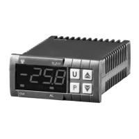
TLZ 11 P
MICROPROCESSOR-BASED
DIGITAL ELECTRONIC
THERMOCONTROLLER
OPERATING INSTRUCTIONS
Vr. 01 (ENG) - 09/05 - cod.: ISTR 06947
TECNOLOGIC S.p.A.
VIA INDIPENDENZA 56
27029 VIGEVANO (PV) ITALY
TEL.: +39 0381 69871
FAX: +39 0381 698730
internet : http:\\www.tecnologic.it
e-mail: info@tecnologic.it
FOREWORD
This manual contains the information
necessary for the product to be installed
correctly and also instructions for its
maintenance and use; we therefore recommend
that the utmost attention is paid to the following
instructions and to save it.
This document is the exclusive property of TECNOLOGIC
S.p.A. which forbids any reproduction and divulgation , even
in part, of the document, unless expressly authorized.
TECNOLOGIC S.p.A. reserves the right to make any formal or
functional changes at any moment and without any notice.
Whenever a failure or a malfunction of the device may cause
dangerous situations for persons, thing or animals, please
remember that the plant has to be equipped with additional
devices which will guarantee safety.
Tecnologic S.p.A. and its legal representatives do not assume
any responsibility for any damage to people, things or animals
deriving from violation, wrong or improper use or in any case
not in compliance with the instrument’s features.
INDEX
INSTRUMENT ORDERING COD
7.5
FUNCTIONAL DATA7.4
MECHANICAL DIMENSIONS, PANEL CUT-OUT AND
MOUNTING
7.3
MECHANICAL DAT
7.2
ELECTRICAL DATA7.1
TECHNICAL DATA7
GUARANTEE AND REPAIR
6.3
CLEANING6.2
SIGNALLING6.1
PROBLEMS , MAINTENANCE AND GUARANTE
6
PROGRAMMABLE PARAMETERS TABLE5
PARAMETERS CONFIGURATION BY KEY014.7
FUNCTION OF KE
“U”4.6
DIGITAL INPUT4.5
EXTERNA
LARM4.4.2
TEMPERATURE ALARMS4.4.1
LARM FUNCTIONS4.4
COMPRESSOR PROTECTION FUNCTION AND DELA
AT POWER-ON
4.3
TEMPERATURE CONTROL4.2
MEASURING AND VISUALIZATION4.1
FUNCTIONS4
ELECTRICAL WIRING DIAGRAM3.4
ELECTRICAL CONNECTION
3.3
MECHANICAL MOUNTING3.2
PERMITTED US
3.1
INFORMATION ON INSTALLATION AND USE 3
ON / STAND-BY FUNCTION2.5
PARAMETERS PROGRAMMING LEVE
2.4
PARAMETER PROTECTION USING THE PASSWORD2.3
PARAMETERS PROGRAMMIN
2.2
PROGRAMMING OF SET POINT 2.1
PROGRAMMING2
FRONT PANEL DESCRIPTION1.2
GENERAL DESCRIPTION1.1
INSTRUMENT DESCRIPTION1
1 - INSTRUMENT DESCRIPTION
1.1 - GENERAL DESCRIPTION
TLZ 11 P is a digital microprocessor based thermocontroller for
Heating or Cooling applications and ON/OFF control mode.
The instrument has up to 2 relay outputs, one input for Pt1000 or
NTC (PT-24C2 up to 300°C) temperature probes and a digital
input, that can be configured.
The 2 outputs can be used for controlling the temperature control
device (OUT) and an alarm (AL).
The instrument is equipped with 4 programme keys, a 4-digit
display and 2 LED signals, in addition to an internal buzzer that is
the sound system for alarms.
Other important characteristics of the instrument are: programme
parameters protection using personalised password, switching on
and off (stand-by) of the instrument using the “U” front key,
configuration of parameters via the KEY 01 device and the
possibility of power supply in the range 100 ... 240 VAC.
1.2 - FRONT PANEL DESCRIPTION
TLZ 11
1
5
2
3
4
Out AL
7
6
1 - Key P : Used for setting the Set point and for programming the
function parameters
2 - Key DOWN : Used for decreasing the values to be set and for
selecting the parameters.
TECNOLOGIC spa - TLZ 11 P - OPERATING INSTRUCTIONS - Vr.01 - 09/05 - ISTR 06947 - PAG. 1