SSR outputs); Reinforced between power supply and relay; No
insulation between supply 12 V and input. No insulation between
input and SSR outputs.
7.2 - MECHANICAL DATA
Housing:
Self-extinguishing plastic, UL 94 V0
Dimensions:
33 x 75 mm, depth 64 mm
Weight:
110 g approx.
Mounting:
Flush in panel in 29 x 71 mm hole
Connections:
2,5 mm
2
screw terminals block
Degree of front panel protection :
IP 65 mounted in panel with
gasket
Pollution situation:
2
Operating temperature:
0 ... 50 °C
Operating humidity:
30 ... 95 RH% without condensation
Storage temperature:
-10 ... +60 °C
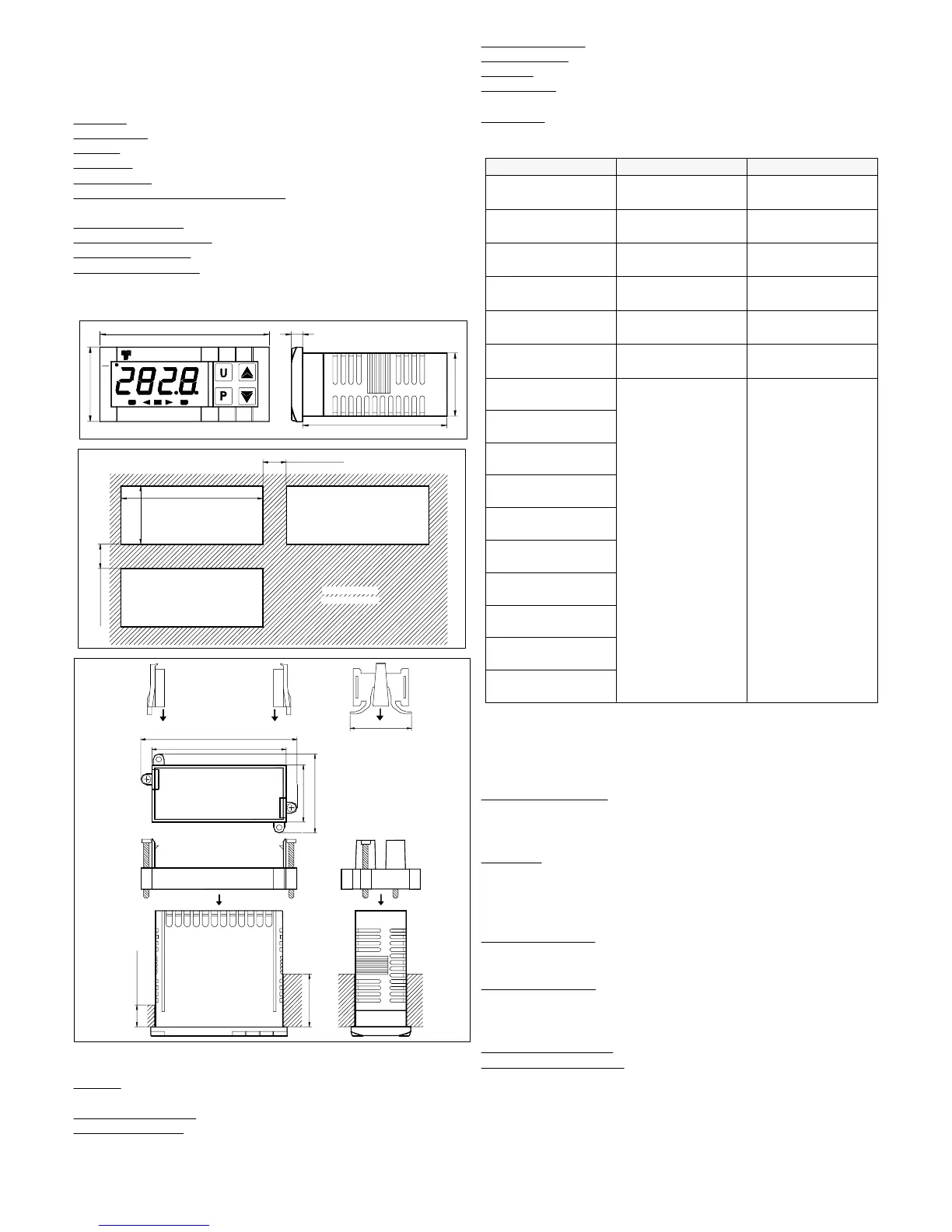
7.3 - MECHANICAL DIMENSIONS, PANEL CUT-OUT AND
MOUNTING [mm]
TLK 38
75
33
5
64
28
ST
AT
OUT2+=-OUT1
RECOMMENDED
PANEL CUTOUT
29
71
min. 15 mm
min. 12 mm
TYPE 1
PANEL + GASKET
PANEL + GASKET
TYPE 2
BRACKET
TYPE 1
BRACKETS
TYPE 2
86
74
43
31
34
MAX 12 mm
MAX 29 mm
7.4 - FUNCTIONAL FEATURES
Control:
ON/OFF, ON/OFF Neutral Zone, PID single Action, PID
double action.
Measurement range:
according to the used probe (see range table)
Display resolution:
according to the probe used 1/0,1/0,01/0,001
Overall accuracy:
+/- 0,5 % fs (tc S: +/- 1 % fs)
Sampling rate:
130 ms.
Display:
4 Digit Red h 12 mm
Compliance:
ECC directive EMC 2004/108/CE (EN 61326), ECC
directive LV 2006/95/CE (EN 61010-1)
Approvals:
C-UL (file n. E206847)
7.5 - MEASURING RANGE TABLE
2 ... 10 V
“SEnS” = 2.10
0 ... 10 V
“SEnS” = 0.10
1 ... 5 V
“SEnS” = 1.5
0 ... 5 V
“SEnS” = 0.5
0 ... 1 V
“SEnS” = 0.1
12 ... 60 mV
“SEnS” = 12.60
0 ... 60 mV
“SEnS” = 0.60
0 ... 50 mV
“SEnS” = 0.50
4..20 mA
“SEnS” = 4.20
-199.9 ... 999.9
-19.99 ... 99.99
-1.999 ... 9.999
-1999 ... 9999
0..20 mA
“SEnS” = 0.20
-50.0 ... 110.0 °C
-58.0 ... 230.0 °F
-50 ... 110 °C
-58 ... 230 °F
NTC (103-AT2)
“SEnS” = ntc
-55.0 ... 150.0 °C
-67.0 ...302.0 °F
-55 ... 150 °C
-67 ... 302 °F
PTC (KTY81-121)
“SEnS” = Ptc
-199.9 ... 850.0 °C
-199.9 ... 999.9 °F
-200 ... 850 °C
-328 ... 1562 °F
Pt100 (IEC)
“SEnS” = Pt1
- - - -0 ... 1760 °C
32 ... 3200 °F
tc S
“SEnS” = S
- - - -0 ... 1370 °C
32 ... 2498 °F
tc K
“SEnS” = CrAl
- - - -0 ... 1000 °C
32 ... 1832 °F
tc J
“SEnS” = J
“dP”= 1, 2, 3“dP” = 0INPUT
7.6 – INSTRUMENT ORDERING CODE
TLK38 a b c d ee f
a : POWER SUPPLY
F = 12 VAC/VDC
L = 24 VAC/VDC
H = 100... 240 VAC
b : INPUT
C = thermocouples (J, K, S, I.R), mV, thermoresistances (Pt100)
E = thermocouples (J, K, S, I.R.), mV, thermistors (PTC, NTC)
I = normalized signals 0/4..20 mA
V = normalized signals 0..1 V, 0/1..5 V, 0/2..10 V.
c : OUTPUT
OUT1
R = Relay
O = VDC for SSR
d
: OUTPUT OUT2
R = Relay
O = VDC for SSR
- = None
ee:
SPECIAL CODES
f: SPECIAL VERSIONS
TLK 38 PASSWORD = 381
TECNOLOGIC spa - TLK 38 - OPERATING INSTRUCTIONS - Vr. 03 - ISTR 06519 - PAG. 12