8-4
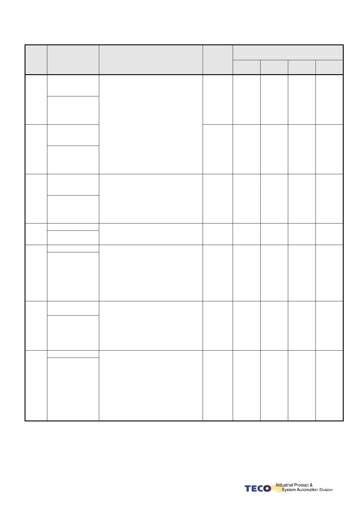
Alarm Status Digital Output
Alarm
Code
Alarm Name
and Description
Corrective Actions
Reset
Method
CN1-25
BB/A3
CN1-24
ST/A2
CN1-23
PC/A1
CN1-22
LM/A0
Encoder ABZ
phase signal
error
05
Motor’s encoder
failure or encoder
connection
problem.
Reset
Power
Supply
1 0 1 0
Encoder UVW
phase signal
error
06
Motor’s encoder
failure or encoder
connection
problem.
1. Check the motor’s encoder
connections.
2. Check the encoder if short circuit,
poor solder joints or break.
3. Check the encoder signal terminals
CN2-1 and CN2-2. ( power cable
5v)
Reset
Power
Supply
1 0 0 1
Multi-function
contact setting
error
07
Input/output
contacts function
setting error.
1. Check parameters Hn601~Hn606,
trigger level selected by 2
nd
digit of
Hn 601 to 606 should be the same
for all inputs DI-1~DI-6.
2.Check parameters setting of Hn613
~ Hn615 should NOT be the same
for outputs contact DO-1~DO-3.
Reset
Power
Supply
1 0 0 0
Memory Error
08
Parameter write-in
error
Disconnect all command cable then
re-cycle the power. If alarm still
occurs, it means the Drive was failure.
Reset
Power
Supply
0 1 1 1
Emergency Stop
09
When the input
contact point EMC
is activated.
Alarm 09 appears
1. Disable Emergency stop signal
input.
2. Internal mal-function.
Ensure that all connection are
correct, refer to Chapter 2 Power
and motor circuit diagrams
connection.
Control wiring diagrams.
Turn
ALRS(DI)
ON
0 1 1 0
Motor
over-current
10
Motor current is 4
times greater than
rated current.
1.Check if the motor wiring U,V,W)and
encoder wiring correct or not.
2.Internal interference and
mal-function. Ensure that all
connection are correct ,refer to
Chapter 2 Power and motor circuit
diagrams.
Turn
ALRS(DI)
ON
0 1 0 1
Position error
11
The deviation
between Pulse
command and
encoder feed back
( position error) is
greater than the
setting of Pn308 or
Pn309.
1. Increase the position loop gain
(Pn310 and Pn311) setting value.
2. Increase in position tolerance value
by (Pn307) for a better motor
response.
3. Extend the time of ac/deceleration
or reduce load inertia in the
permitted range.
4. Check if the motor wiring (U,V,W)
is correct.
Turn
ALRS
(DI)
ON
0 1 0 0
 Loading...

