EasyManua.ls Logo

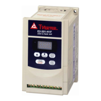
TECO T-Verter E2-202-H1F User Manual

TECO T-Verter E2-202-H1F
64 pages
To Next Page IconTo Next Page
Page #1 background imageLoading...
Page #1 background image
E2 Adjustable Speed Driver
Microprocessor Controlled
IGBT Drive
Inverter Motor Speed Regulator
Operating Manual
High Performance Adjustable Speed Micro Drives
E2 Series
110V
0.2~0.75KW
( 0.53~1.6KVA )
220V
0.2~2.2KW
( 0.53~4.0KVA )
440V
0.75~2.2KW
( 1.7~4.0KVA )

Table of Contents

Question and Answer IconNeed help?

Do you have a question about the TECO T-Verter E2-202-H1F and is the answer not in the manual?

TECO T-Verter E2-202-H1F Specifications

General IconGeneral
Horsepower2 HP
Input Frequency50/60 Hz
Output Power1.5 kW
Control MethodV/F control
Overload Capacity150% for 60 seconds
Enclosure RatingIP20
Input Voltage200-240V AC
Protection FeaturesOvercurrent, Overvoltage, Undervoltage, Short Circuit
Communication InterfaceRS-485
Operating Temperature-10°C to +50°C
Cooling MethodFan

Summary

Preface

Precautions

Safety warnings and symbols for inverter use, including danger and caution notices.

Chapter 1 Safety Precautions

1. Operation Precautions

Critical safety guidelines for operating the inverter, covering power-up and general use.

1.1 Before Power Up

Specific safety steps to follow before applying power to the inverter.

1.2 When power is applied

1.3 During operation

1.4 Useable environment

Guidelines for suitable environmental conditions for inverter installation and operation.

2. Precautions of operation environment

Chapter 2: Hardware Instructions and Installation

1. Operational Environment

Detailed requirements for the installation site to ensure inverter functionality and longevity.

3. Specification:

Basic specification:

Presents fundamental technical specifications for different inverter models.

Functional specification:

Wiring Diagram and Specifications

Inverter terminal descriptions

E2-1P2/1P5/101/2P2/2P5/201- - N4X(IP65)TYPE INSTALLATION :

E2-1P2~201--N4 (WITHOUT SWITCH TYPE) CONNECTIONS & EMC MOUNTING:

E2-1P2~201--N4S (WITH SWITCH TYPE) EMC MOUNTING & CONNECTIONS :

E2-202/203/401/402/403—N4X(IP65)TYPE INSTALLATION:

CIRCUIT DIAGRAM

Schematic diagram for the circuit connections of specific inverter models.

Parameter List

Parameter function description

F_03: Operation mode selection

F_04: Motor rotation direction setting

F_05: V/F pattern setting

F_06: frequency upper limit

F_07: frequency lower limit

F_10: Start / Stop Control

F_11: Speed Control

F_12: Carrier Frequency

F_13: Torque compensation gain

F_14 Stopping method

F_15 DC braking time

F_16 DC braking starting frequency

F_17 DC braking level

F_18: Motor rated current

1. The electronic thermal overload protection for motor:

2. The electronic thermal protecting for inverter:

F_19: Multifunctional input terminal 1 function

F_20: Multifunctional input terminal 2 function

F_19, F_20 =3: External emergency stop

F_19, F_20 =4: External Base Block (Immediate Shut Down)

F_21: Multi-function output terminal control

F_22: Reverse Lock-Out

F_23: Auto-restart after momentary power loss

F_24: Number of Auto-restart times

F_25: Return to Factory Pre-Settings

F_26: SP2(1~200Hz) , Multi-speed2

F_27: SP3(1~200Hz) , Multi-speed3

F_28: Direct start

F_30: Last three faults

Malfunction Indications and Countermeasures

1. Manual reset inoperative malfunctions

Lists malfunctions that do not reset automatically and their remedies.

2. Manual reset operative malfunctions (Auto-Reset inoperative)

Lists malfunctions that require manual reset or have inoperative auto-reset features.

3.Manual Reset and Auto-Reset Operative Malfunction

Special Condition Description

Keypad Operation Error Instruction

General Malfunction Examination Method

Chapter 4:Troubleshooting Procedures

Inverter Malfunction

General flowchart for diagnosing inverter malfunctions.

(Continued)

Error handling of malfunction indication of OC.OL

Error handling of malfunction indication of OV.LV

(1). Motor inoperative

(2).Motor over-heat

(3).Disturbing motor operation

Routine examination and periodical examination

Maintenance and Examination

Voltage Current Measurement

Related product manuals