Technical equipment of TC600 PLC
53 TXV 138 08.02
Binding circuits of the interface are led out to connectors K1 to K6 of the
terminal board marked as SERIAL CHANNEL 1.
Connector Signal Signal type Use
K1 frame connection of the
shielding
K2, K4 RxD-/TxD- input/output data signal
K3, K5 RxD+/TxD+ input/output data signal
K6 GND signal ground
Interconnection is realized by a couple of twisted shielded conductors. In
general, it holds that for higher communication speeds and greater lengths
of cables, it is necessary to use higher cross section of conductors. For re-
duction of reflections, the line is impedance-adjusted by terminators on both
ends of the line. In some cases, it is necessary to interconnect signal
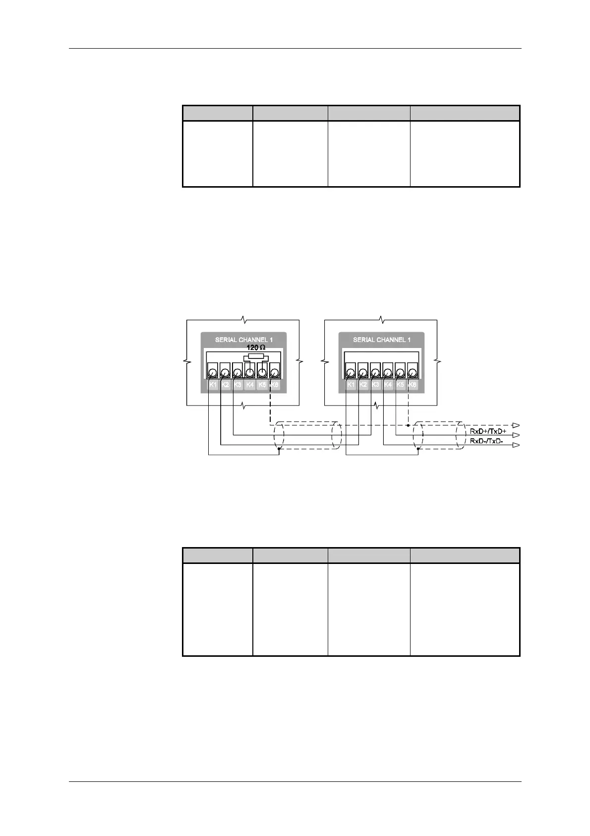
grounds to balance their potentials. In Fig. 9.25, scheme of interconnection
of the RS-485 interface at the marginal and internal equipment of the net-
work is indicated.
Internal network equipmentMarginal network equipment
Fig. 9.25 Interconnection of two CH1 interfaces RS-485 of the PLC of
TC600 series
Binding circuits of the interface are led out to connectors K1 to K6 of the
terminal board marked as SERIAL CHANNEL 1.
Connector Signal Signal type Use
K1 frame connection of the
shielding
K2 TxD- output data signal
K3 TxD+ output data signal
K4 RxD- input data signal
K5 RxD+ input data signal
K6 GND signal ground
Interconnection is realized by two couples of shielded twisted conductors.
In general, it holds that for higher communication speeds and greater
lengths of cables, it is necessary to use greater cross section of the con-
ductors. For reduction of reflections, the line is impedance-adjusted by ter-
minators on the side of the receivers. In some cases, it is necessary to in-
terconnect the signal grounds to balance the potentials. In Fig. 9.26,
scheme of interconnection of two RS-422 interfaces is indicated.
Optional CH1 RS-485
interface
Lead out of binding
circuits of piggybacks
MR-04, MR-09 of
CH1
Optional CH1 RS-422
interface
Lead out of binding
circuits of the
piggyback MR-17 of
CH1


 To Next Page