Tecomat TC600
TXV 138 08.02 56
9.5.11 Connection of the CH3 Interface
Binding circuits of the interface are led out to connectors P1 to P5 of the
terminal board marked as OPTIONAL I/O.
Lead out Signal Signal type Use
P1 TxD output data signal
P2 RTS output controlling signal
1)
P3 RxD input data signal
P4 CTS input controlling signal
1)
P5 GND signal ground
1)
Use of the signal is described in the handbook
Serial Communication of
Tecomat Programmable Logic Controllers, TXV 001 06.02
. Still level of the
signal corresponds with the value logical 1.
Interconnection is realized in the way described under item 9.5.10.
Binding circuits of the interface are led out to connectors P6 to P10 of
the terminal board marked as OPTIONAL I/O.
Connector Signal Signal type Use
P6, P8 RxD+/TxD+ input/output data signal
P7, P9 RxD-/TxD- input/output data signal
P10 GND signal ground
Interconnection is realized in the way described under item 9.5.9.
9.5.12 Connection of Interrupt Inputs
Interrupt inputs are connected identically as common binary inputs (see
item 9.5.3).
9.5.13 Connection of the Type 3 Counter
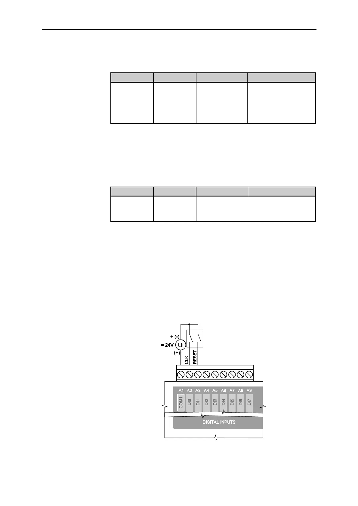
Source of counted events and the controlling signal are connected be-
tween the common connector A1 (COM1) and connectors A2 (DI0) and A3
(DI1) in the way illustrated in the scheme in Fig. 9.29. In the case that the
RESET input is not used, it must be serviced by connection to voltage cor-
responding with log. 1.
Fig. 9.29 Connection of the type 3 counter of the PLC of TC600 series
CH3 RS-232 interface
Lead out of binding
circuits of the piggy-
back MR-15 of CH3
CH3 RS-485 interface
Lead out of binding
circuits of the piggy-
back MR-14 of CH3


 To Next Page