Technical equipment of TC600 PLC
55 TXV 138 08.02
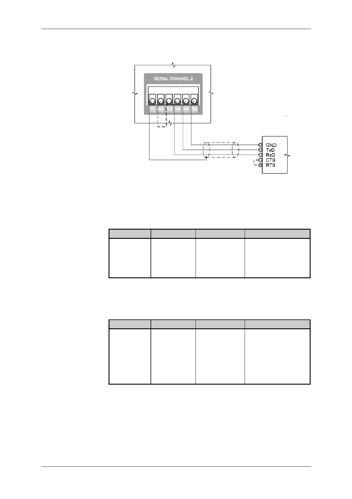
Fig. 9.28 shows three-conductor interconnection of data binding circuits.
The dashed line indicates formation of the RTS-CTS loop.
Interface of
the connected
device
Fig. 9.28 Three-conductor interconnection of the CH2 interface RS-232 of
the PLC of TC600 series
Binding circuits of the interface are led out to connectors N1 to N6 of the
terminal board marked as SERIAL CHANNEL 2.
Connector Signal Signal type Use
N1 frame connection of the
shielding
N2, N4 RxD-/TxD- input/output data signal
N3, N5 RxD+/TxD+ input/output data signal
N6 GND signal ground
Interconnection is realized in the way described under item 9.5.9.
Binding circuits of the interface are led out to connectors N1 to N6 of the
terminal board marked as SERIAL CHANNEL 2.
Connector Signal Signal type Use
N1 frame connection of the
shielding
N2 TxD- output data signal
N3 TxD+ output data signal
N4 RxD- input data signal
N5 RxD+ input data signal
N6 GND signal ground
Interconnection is realized in the way described under item 9.5.9.
Optional CH2 RS-485
interface
Lead out of binding
circuits of piggybacks
MR-04, MR-09 of
CH2
Optional CH2 RS-422
interface
Lead out of binding
circuits of the
piggyback MR-17 of
CH2


 To Next Page