Tecomat TC600
TXV 138 08.02 52
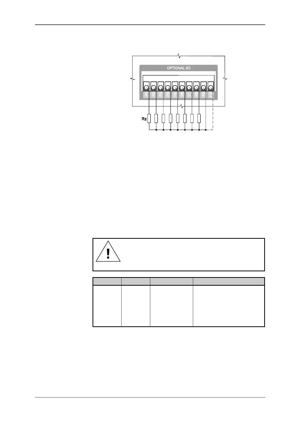
In Fig. 9.24, scheme of connection of loads to the OT-14 piggyback
analog outputs is indicated.
Fig. 9.24 Connection of loads to the OT-14 piggyback analog outputs
Examples of the installation realization in the distribution board are con-
tained in the handbook
Design of Tecomat Programmable Logic Controllers,
TXV 001 08.02.
For fitting of terminal boards of analog outputs of individual PLC types
see Article 9.4.
9.5.9 Connection of the CH1 Interface
Interface RS-232 of CH1 is designed especially for connection of a com-
puter of the PC class performing the function of a programming device.
Binding circuits of the interface are led out to the 9-pole socket Dsub
(CONNECTOR L) marked as SERIAL CHANNEL 1/RS-232. The connection
is realized by the cable TXK 646 51.06 ended on the PC side by the 9-pole
Dsub socket.
If the optional CH1 interface is fitted, by connecting the
cable TXK 646 51.06, signals of CH1 will be disconnected
automatically from the optional interface.
Lead out Signal Signal type Use
L2 RxD input data signal
L3 TxD output data signal
L5 GND signal ground
L7 RTS output controlling signal
1)
L8 CTS input controlling signal
1)
L9 232DIS input CH1 interface switch
1)
Use of the signal is described in the handbook
Serial Communication of
Tecomat Programmable Logic Controllers, TXV 001 06.01.
Still level of
the signal corresponds with the value of logical 1.
CH1 RS-232 interface
Signals of the CH1
RS-232 interface


 To Next Page