Remote Condensing Unit Installation Instructions
Lifting/Handling Instructions
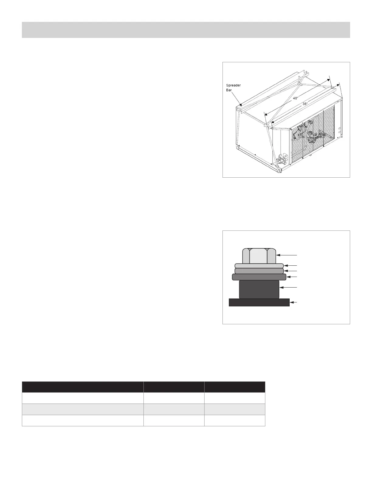
When a crane is used to lift the unit proper measures should be taken to protect the
enclosure panels. The application of spreader bars are strongly recommended to prevent
damages to the sides. (See Figure 2) Some care should be taken to locate the center
of gravity before lifting. The compressor, which is the heaviest part of the unit may not be
located in the center of the unit base.
Never lift or displace the outdoor units with enclosure panels removed. All the panels should
be in place and properly tightened. Don’t remove the shipment pallet until the unit arrives at
the final destination. If unit has to be re-located use a proper pallet to carry the unit.
Ground Mounting
Concrete slab raised six inches above ground level provides a suitable base. Raising the
base above ground level provides some protection from ground water and windblown
matter. Before tightening mounting bolts, recheck level of unit. The unit should be
located with a clear space in all directions that is at a minimum, equal to the height of
the unit above the mounting surface. A condensing unit mounted in a corner formed
by two walls, may result in discharge air recirculation with resulting loss of capacity.
Roof Mounting
Due to the weight of the units, a structural analysis by a qualified engineer may be
required before mounting. Roof mounted units should be installed level on steel
channels or an I-beam frame capable of supporting the weight of the unit. Vibration
absorbing pads or springs should be installed between the condensing unit legs or
frame and the roof mounting assembly.
Snow
If snow is a possibility, mount unit to ensure access for maintenance and
proper air flow.
Rigid Mount Compressors
Check the compressor mounting bolts to ensure they have not vibrated loose
during shipment. (See figure 3)
Figure 3
ELECTRICAL CONNECTIONS
In order that these units have the starting, operating and dependability characteristics required of them, the
compressor and its protective devices are designed for operation within a very specific minimum and maximum
voltage range. This voltage range is defined in the following table:
Verify before any electrical installation if the voltage and phases of the supply satisfy those required of the unit.
Voltage shown on Unit Nameplate Voltage Code Voltage Range
115 - 115/60/1 AA 103 - 127
208 - 230/60/1 NA 254 - 187
200 - 230/60/3 TB 254 - 180
Figure 2
Machine Screw
Washer
Mounting Grommet
Compressor Mounting
Mounting Grommet
Base Plane