5
Remote Condensing Unit Installation Instructions
©2019 Tecumseh Compressor Company LLC. All rights reserved. TPC Part #71511 | Rev A 05/13/2019www.tecumseh.com
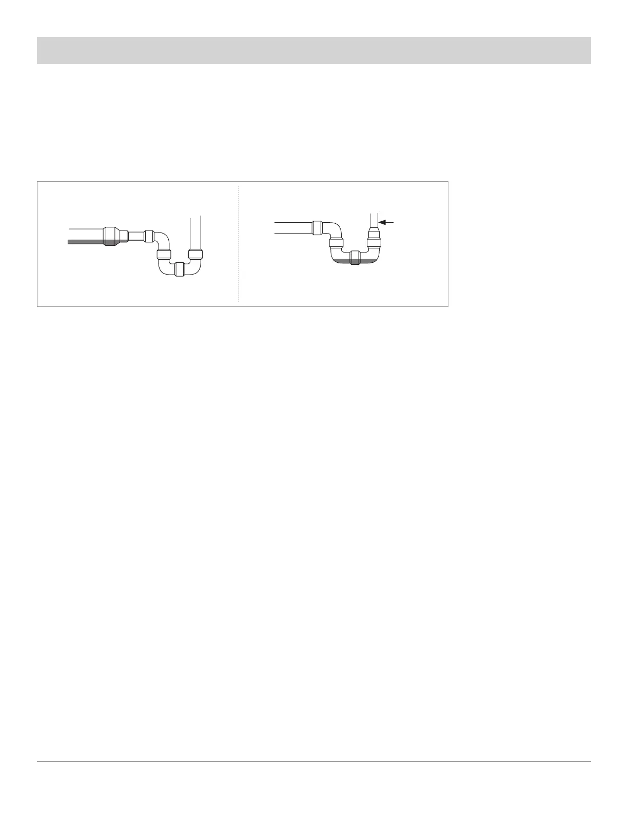
one regular ell. The suction trap must be the same size as the suction line. For long vertical risers, additional traps
may be necessary. Generally, one trap is recommended for each length of pipe (approximately 20 feet) to insure
proper oil movement. See Figure 4 for methods of constructing proper suction line P-traps. Suction line lengths in
excess 100 feet may require additional oil be added to the compressor.
Figure 4
B) Liquid line sizes are based on pressure drops that will not permit gas formation for horizontal lengths up to
100’. For lines longer than 100’ horizontal and for lines that travel up vertically additional sub-cooling must be
provided to overcome the vertical liquid head pressures and extra length. Liquid refrigerant in vertical column
will exert a downward pressure of 0.5 – 0.6 pounds per linear foot of tube, and depending upon the direction of
the refrigerant flow, will either add or subtract from the liquid line pressure drop.
Liquid lines should be sized for a minimum pressure drop to prevent ‘’flashing”. Flashing in the liquid lines
would create additional pressure drop and poor expansion valve operation. If a system requires long liquid lines
from the receiver to the evaporator or if the liquid must rise vertically upward any distance, the losses should
be calculated to determine if a heat exchanger is required or not. The use of a suction to liquid heat exchanger
may be used to subcool the liquid to prevent flashing. This method of subcooling will normally provide no more
than 20°F subcooling on high pressure systems. The amount of subcooling will depend on the design and size
of the heat exchanger and on the operating suction and discharge pressures. An additional benefit from the use
of the suction to liquid type heat exchanger is that it can help raise the superheat in the suction line to prevent
liquid return to the compressor via the suction lines. Generally, heat exchangers are not recommended on
R407A, R448A, R449A systems, however, they have proved.
C) Elbows, valves and reduced joint sizes increase pressure drop and deserve additional consideration.
D) Long radius elbows should be employed to minimize pressure losses.
E) To prevent oxidation and scale forming inside the tubes it is recommended to flow dry nitrogen through
the tubing during the soldering operations. A light flow of about ¼ CFM is sufficient.
F) Follow the manufacturer’s instructions when brazing service valves or other parts that may be damaged
by excessive heat.
G) After all leak check procedures are complete, refrigerant lines that may be exposed to high and low
ambient temperatures should be insulated. As a rule of thumb, suction lines should be insulated with an
industry accepted material of no less than ¾” wall thickness. Liquid lines should also be insulated with at least
½” wall thickness. The insulating material should be of a kind intended for outdoor use.
Suction P-Traps
Incorrect
Slope 1/4”
per 10 ft.
downward toward
the compressor
Reduc
Here
Correct
Oil
Oil