80
14. Remove the internal components. Align the timing
marks on all engines except VM70, 80, 100, HHM80,
HM70, 80, 100, TVM170, 195, 220 to relieve valve
lifter pressure. On these engines it is necessary to
rotate the camshaft clockwise three (3) teeth past
the aligned position to allow the compression release
mechanism to clear the exhaust valve lifter and to
allow the camshaft to be removed (diag. 19 & 20).
TIMING MARK
19
20
OIL SLEEVE TOOL
MOUNTING FLANGE
OIL SEAL
SNAP RING
OIL SEAL REMOVED
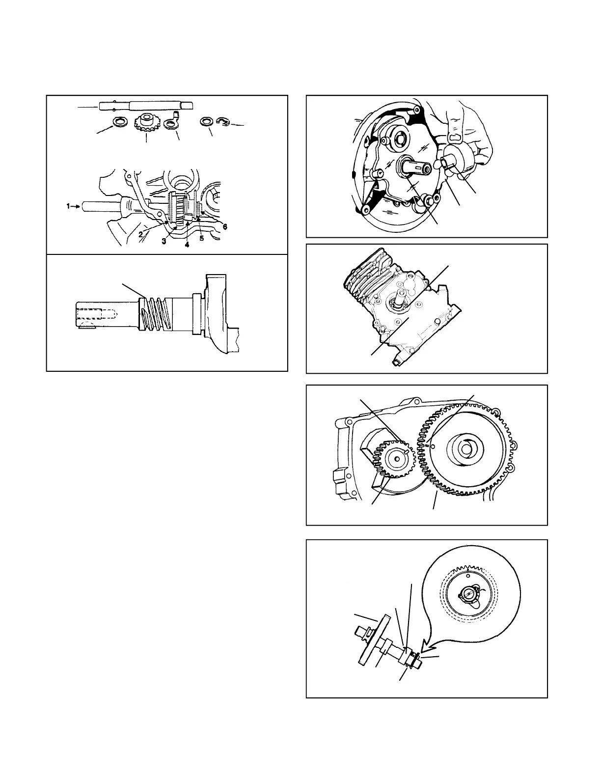
13. Remove the cylinder cover or mounting flange using a seal protector positioned in the seal to prevent seal damage.
The crankshaft must be free of rust or scale to slide the cover off the crankshaft. H30-HS50 horizontal crankshaft
engines with ball bearings on the crankshaft require the oil seal and the snap ring to be removed prior to the cylinder
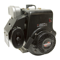
cover removal. On engines equipped with 8 1/2:1 gear reduction, turn the crankshaft to roll the reduction shaft gear
off the crankshaft worm gear when removing the cylinder cover (diag. 15, 16, 17, 18).
WORM GEAR
15
17
16
18
BEVELED TOOTH
CAMSHAFT GEAR
CRANKSHAFT
GEAR
15. Remove the lifters, rod cap, and balance shaft or gears
if applicable.
16. Before removing the piston, remove any carbon from
the top of the cylinder bore to prevent ring breakage.
Push the piston out the top of the cylinder bore.
17. Remove the valves by using a valve spring
compressor to compress the valve spring and rotate
the valve spring retainer to allow the valve stem to
pass through. Lift the valves out of the cylinder block.
Remove the spring assemblies being careful to note
the differences, the original placement of the springs
and the presence of seals. Reinstall the spring
assemblies on the same valve in the reverse order
as they are removed.
EXHAUST CAM
ROLL PIN
CAM GEAR
SPRING
INTAKE CAM
PLUNGER (COMPRESSION RELIEF PIN)
1. PTO
Shaft
2. Thin
Washer
3. Gear
4. Tang
Washer
5. Thick
Washer
6. Retainer
 Loading...