EasyManua.ls Logo

TeeJet 855 - User Manual

Default Icon
40 pages
Print Icon
To Next Page IconTo Next Page
Loading...
Installation,
Programming
and Operating
Manual

Questions and Answers

  • B
    Brendan AndradeAug 15, 2025
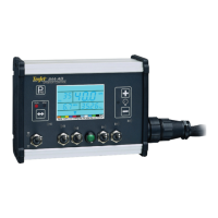
    Why do the application rate units flash on my TeeJet Controller?
    • M
      millerchristinaAug 15, 2025
      The application rate units might be flashing because there's a continuous discrepancy of 10% or more between the target and actual application rate. To resolve this, check all components and programming steps related to flow.
  • S
    Sarah McintoshAug 18, 2025
    What to do if the pump capacity is too low on my TeeJet Controller?
    • J
      Jessica CarrollAug 18, 2025
      If the pump capacity is too low, verify the pump is working correctly. Also, inspect the plumbing system for any obstructions and consider reducing the agitation volume.
  • A
    Amber MayerAug 22, 2025
    Why is the pump capacity too high on my TeeJet Controller?
    • M
      Michael FloresAug 22, 2025
      Some centrifugal pumps provide more flow than necessary for the application. A throttle valve may be required to restrict the flow coming from a centrifugal pump.
  • U
    umorrisonAug 26, 2025
    How to fix no speed sensing on my TeeJet Controller?
    • B
      Bruce PetersonAug 26, 2025
      Check the speed sensor to ensure it is sending pulses to the controller.
  • T
    Teresa RichmondAug 28, 2025
    What to do if the tips are plugged on my TeeJet Controller?
    • T
      Tara BrownAug 28, 2025
      If you have plugged nozzles, remove them from the boom and clean them with water and a TeeJet brush.
  • K
    Kayla MartinezAug 31, 2025
    What to do if the flow meter is stalled on my TeeJet Controller?
    • S
      Sarah DavisAug 31, 2025
      Make sure there is no pressure in the system. Remove the flow meter from the discharge line and inspect the inside of the meter for obstructions. The turbine should move freely; if not, try flushing it out with clean water.
  • E
    Eric JonesSep 4, 2025
    How to correct a flow meter plumbed incorrectly in TeeJet Controller?
    • M
      Misty McbrideSep 4, 2025
      A flow directional arrow is located on the body of the flow meter. Plumb the flow meter with the arrow in the direction of the flow.
  • A
    antonio16Sep 7, 2025
    What causes extreme low regulated flow on my TeeJet Controller and how to fix it?
    • S
      Sara SmithSep 7, 2025
      Extreme low regulated flow can occur due to very low application rates, causing the regulating valve in throttling mode to operate in an almost closed position. Adjust the Reg. Valve Speed Number in the System Setup Mode to a slower value.
  • A
    Andre ShawSep 12, 2025
    How to troubleshoot regulating valve malfunction on TeeJet Controller?
    • P
      pmarksSep 12, 2025
      Check wiring from controller to the regulating valve.

Summary

Introduction

Mounting Sprayer Components

PRESSURE REGULATOR IN BYPASS MODE

Details the setup for the pressure regulator when plumbed in a bypass system.

PRESSURE REGULATOR IN THROTTLING MODE

Explains how to mount and configure the pressure regulator in a throttling system.

FLOW METER

Provides guidelines for installing and positioning the flow meter for accurate readings.

BOOM CONTROL VALVES

Describes the connection and mounting of boom control valves for sprayer sections.

PRESSURE TRANSDUCER

Covers the installation of the pressure transducer near spray tips to minimize pressure drop.

Installing the Speed Sensor Assembly

Location

Specifies installing the speed sensor on a non-driven wheel to avoid errors from slipping.

Proximity Sensor (optional)

Details the installation of an optional proximity sensor for limited space or drive shaft mounting.

Installing the Wheel Magnets

Guides on drilling holes and mounting magnets on the wheel rim for speed sensing.

Installing the Magnetic Sensor

Instructions for mounting the magnetic sensor and positioning it relative to wheel magnets.

Confirming Speed Sensor Installation

How to test the installed wheel or proximity speed sensor for proper function.

Mounting the TeeJet 844 Console

Location

Guidance on selecting the optimal placement for the control console within the operator's compartment.

Mounting

Instructions for securely mounting the console to a firm support using provided brackets.

Power Connection

Connecting Component Cables

Wiring Layout

Making the Connections

Programming Guidelines

IMPORTANT PRELIMINARY INFORMATION

Essential guidelines and tips to review before beginning the programming process.

Steps to Successful Programming

SYSTEM SETUP MODE

Setting Your Program Mode (U.S., Turf, NH3, Imperial, S.I.)

Configures the system's measurement units for application rate and other parameters.

Reset Defaults?

Option to reset all programming values to the factory default settings for selected units.

Flow Meter or Pressure Based

Selects whether flow regulation is controlled by a flow meter or pressure transducer.

Flow meter Pulses

Calibrates the flow meter by entering its pulse rate per unit of liquid.

Pressure Transducer Maximum Rating (P Hi)

Sets the maximum pressure rating for the installed pressure transducer.

Pressure Transducer Low Pressure Calibration (PrEF)

Calibrates the zero pressure setting of the pressure transducer for accurate readings.

Nozzle Spacing

Enters the spacing between spray tips on the boom for accurate application calculations.

Number of Spray Tips Per Boom Section

Configures the number of spray tips for each boom section to match the sprayer setup.

User Programmable Tip

Allows inputting flow rate data for custom spray tips not pre-programmed in the system.

Pressure Regulating Mode

Specifies how the pressure regulating valve is plumbed (bypass or throttling).

Coarse Regulation Adjustment Speed

Sets the speed for coarse adjustments of the pressure regulating valve.

Fine Regulation Adjustment Speed

Sets the speed for fine-tuning adjustments of the pressure regulating valve.

Boom Control Valve Type

Distinguishes between 2-way and 3-way boom control valves used on the sprayer.

Speed Sensor Calibration

Calibrates the speed sensor by determining pulses per distance traveled.

RADAR SPEED PULSES

Covers calibration for radar-based ground speed sensors.

Distance Counter

Explains the feature to measure distance for field mapping or calibration checks.

Simulated Ground Speed

Allows testing system functions by simulating ground speed without actual sprayer movement.

Liquid Specific Gravity (Density)

Configures the system for the specific gravity of the sprayed liquid for accurate calculations.

Communications

Selects communication options like printing, GPS, or data logging.

Minimum Regulating Pressure Setting

Sets the minimum pressure the sprayer control will regulate to.

APPLICATION SETUP MODE

Target Application Rate

Sets the desired application rate for the spraying operation.

Nozzle Selection

Selects the spray tip color or capacity to match the nozzles used on the sprayer.

Calculation;What If? Step

A diagnostic tool to test different pressure or speed values for application planning.

Operating Instructions

SPRAYER CHECKOUT

Procedures to check sprayer connections, sensors, and spray tips before operation.

THE SPRAYING OPERATION

Guides on how to perform the actual spraying operation with the control system.

Features

BOOST MODE

Allows temporary increase or decrease of application rate by 10% increments during spraying.

AREA;VOLUME FEATURE

Tracks treated acres and total volume applied, dependent on nozzle spacing and flow meter.

FLOW RATE FEATURE

Displays the real-time flow rate measured by the flow meter.

APPLICATION ALARM

Alerts the operator to significant discrepancies between target and actual application rates.

NO FLOW ALARM

Warns the operator if the flow meter stops sending pulses, indicating a potential issue.

PRINTING

Instructions for printing spraying reports using an optional printer.

Troubleshooting Guide

Application Rate Units (GPA, G;1000 ft² or I;Ha) continually flash on;off.

Addresses issues causing application rate units to flash due to discrepancies or programming errors.

Application Rate Units continually flash on;off.

Further troubleshooting for application rate unit flashing, including mechanical causes.

Flow meter turbine symbol continually flashes on;off.

Diagnoses problems with the flow meter turbine symbol flashing, indicating stalling or incorrect plumbing.

Rate Oscillation

Explains causes for application rate fluctuations and how to adjust regulating valve speed.

Sprayer stops spraying while in Auto Mode.

Troubleshooting steps for when the sprayer stops operating in automatic mode.

Actual total volume applied in GPA, G;1000 ft², or I;Ha does not match the total area covered.

Addresses mismatches between total volume applied and area covered, often due to sensor calibration.

No regulation in Auto Mode

Troubleshoots issues where the system fails to regulate pressure or flow in automatic mode.

Flow Meter Calibration

Method 1 - Known Volume

Guides recalibrating the flow meter using a known volume of water.

Method 2 - Known Tip Size Method

Explains how to calibrate the flow meter by comparing measured flow to calculated flow based on tip size.

Flow Meter Maintenance

DAILY MAINTENANCE

Routine cleaning and checks for the flow meter sensor and assembly.

LONG TERM MAINTENANCE

Periodic maintenance procedures for the flow meter, including cleaning in detergent.

Terms and Conditions of Sale

WARRANTIES

States the seller's warranties regarding product performance and non-infringement.

LIMITATION ON LIABILITIES

Limits seller's liability for losses or damages to the billed amount.

COMPLETE AGREEMENT

States that the document constitutes the entire agreement between buyer and seller.

GOVERNING LAW

Specifies the governing law and jurisdiction for the agreement.

TeeJet 855 Specifications

General IconGeneral
BrandTeeJet
Model855
CategoryController
LanguageEnglish

Related product manuals