1
REVISIONS
ENGR
DATE
REV
SHT
ZONE
DESCRIPTION
NMS
10/18/2017
A
1
8D
A1: RELEASE FOR PATENT
PARTS LIST
ITEM
QTY
NET DIMENSIONS/DESCRIPTION
NOTE
MATERIAL
SHT
REVISION STATUS
SHT
1
REV
A
8
A
1234567
D
C
B
C
A
D
B
5 3 16 248 7
8
A
1234567
D
C
B
C
A
D
B
5 3 16 248 7
FitForm Resistance Knob Arrows Template with outer knob
SHEET 1 OF 1
REV
PROJECT:
DRAWN
UNLESS OTHERWISE NOTED
SURFACE ROUGHNESS PER ANSI B46.1
DIMENSIONING PER ASME Y14.5-2009
WELD SYMBOLS PER AWS A2.4
FINISH:
UOS 63RMS ON
MACHINED
SURFACES OR
AS PROCURED
.X
.XX
.XXX
ANGLE
EXPECTATIONS PROPRIETARY
THE INFORMATION CONTAINED HEREIN
IS PROPRIETARY TO EXPECTATIONS AND
SHALL NOT BE REPRODUCED IN WHOLE
OR IN PART OR USED FOR ANY PURPOSE
EXCEPT WHEN SUCH USER POSSESSES
DIRECT WRITTEN AUTHORIZATION
FROM EXPECTATIONS LLC
SCALE: FULL
SIZE:
D
A
TOLERANCES
UNLESS NOTED
=
.1
=
.03
=
.005
=
1
NICK SOLLER
FILLET RADII: .005-.010
CORNER BREAK: .005-.010
ALL DIMENSIONS IN INCHES
EXPECTATIONS LLC
PUYALLUP, WA 98391
DRAWING
PROJECT NAME HERE
FIGURE 4
ADJUST SETTINGS
USER GUIDE
RESISTANCE
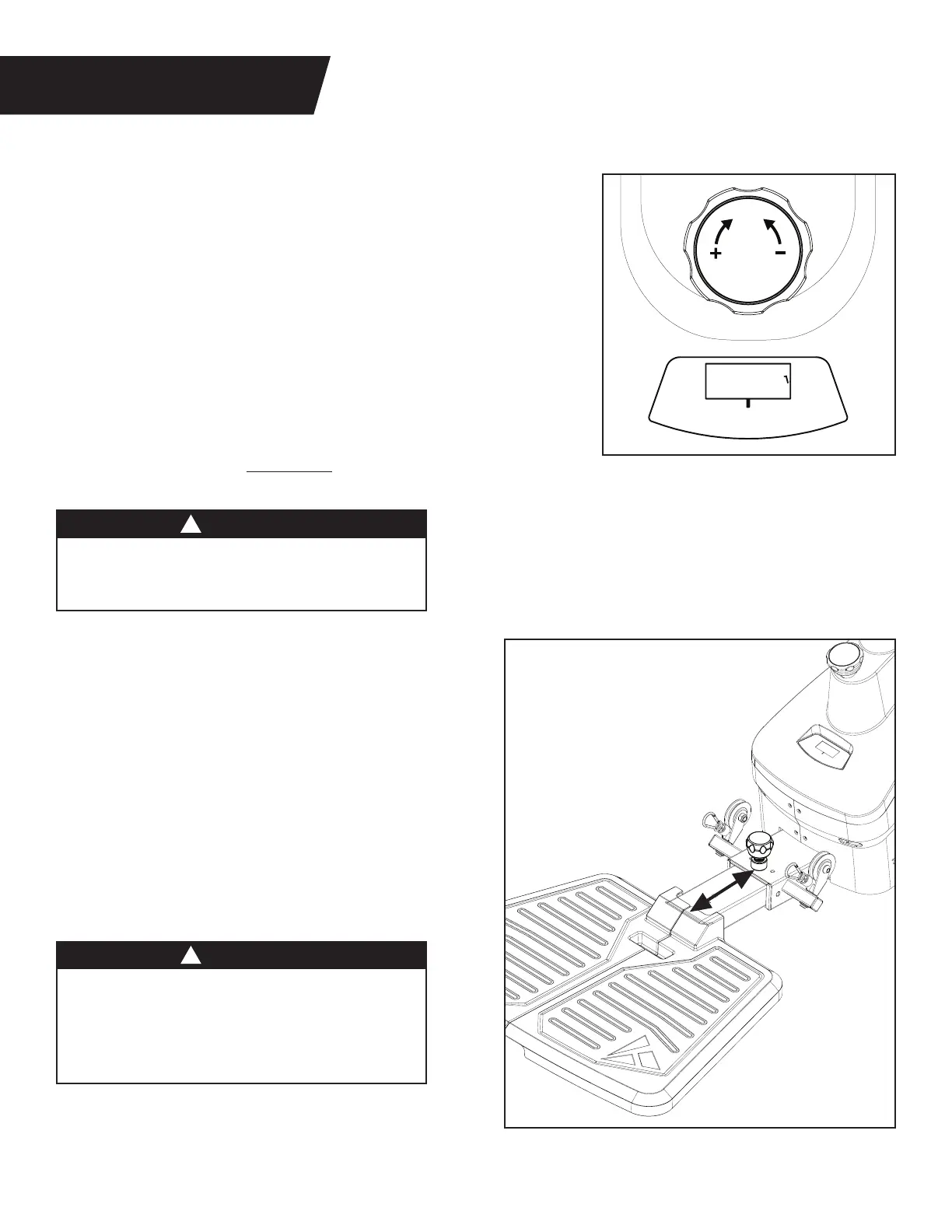
Figure 17: Turn the Resistance Dial clockwise to increase resistance
and counter‑clockwise to reduce resistance.
The numbers on the Resistance Display do not correlate to weight
in pounds. The dial displays resistance levels ranging from 1‑24.
The higher the number, the more resistance is applied to the cable.
The maximum resistance is approximately 65 lb.
NOTE: Due to the nature of the resistance mechanism,
each turn of the Resistance Dial creates a non linear increase
in the resistance felt by the user. This means that one turn of
the Resistance Dial at Level 1 will increase the resistance less
than one turn of the Resistance Dial at Level 24. This also means
that the dial will require more force to turn as the settings increase.
• ALWAYS test the resistance level at the lowest
setting first. Slowly increase resistance as you
feel safe and comfortable to do so without pain.
• ALWAYS test your balance before performing
an exercise after adjusting the Platform length.
• ALWAYS use this machine with at least one
foot or body part on the platform to prevent
instability of the machine or physical injury.
PLATFORM LENGTH
Figure 18: The Platform can be adjusted to three
positions. Setting 1 is the standard setting for
most exercises and users.
Increase the length of the platform to center your
weight on the platform for taller users, or when
performing exercises that require more distance
from the Support Handle.
Refer to the Assembly Instructions on page 8 for
details on how to adjust the Platform length.
Figure 17
Figure 18
WARNING
WARNING
!
!
10
 Loading...