- 9 -
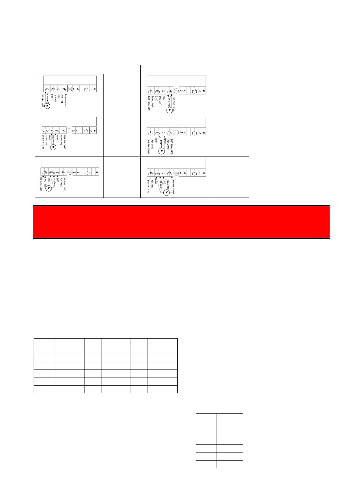
Prior to powering up it is strongly recommended to check the wiring at the sensor terminals of the socket with an
ohmmeter before plugging the controller into the socket. The expected electrical resistance values can be found
below in the instructions in section "Characteristic values of sensors". With a single sensor connected, perform
the checks shown in the left column of the table, and with two sensors connected perform the checks in both
columns.
Resistance
value
Temperature
sensor (see
instructions)
Resistance
value
Temperature
sensor (see
instructions)
Resistance
value
Moisture
sensor (see
instructions)
Resistance
value
Moisture
sensor (see
instructions)
infinite
resistance
(no
connection)
infinite
resistance
(no
connection)
Do not connect a wire of a temperature measurement circuit to a terminal of a moisture measurement circuit! Do
not connect both circuits! This may cause the immediate destruction of the sensor and/or the controller. We
strongly recommend to check the wiring before inserting and powering up the controller. A damage of the
sensor or controller as a result of faulty wiring will not be accepted as a case of warranty.
Switching off the heating system
If there is a central switch-off function for the whole heating system, also the power supply of the ice
and snow detector must be included. If this is not the case, there is the danger that a snow and ice
condition is not detected when the heating system is switched on.
Characteristic values of sensors
In order to measure the sensor values, disconnect the ice and snow detector from voltage and remove it
from the socket!
Temperature sensor
Moisture sensor
The sensor cables connected to the T1/T1 und
T2/T2 terminals can be measured with the help
of an ohmmeter.
The table on the left shows the relationship
between sensor temperature and sensor
resistance.
For a fully functional moisture sensor the resistance
value between the two terminals M1/M1 or M2/M2 is: