- 6 -
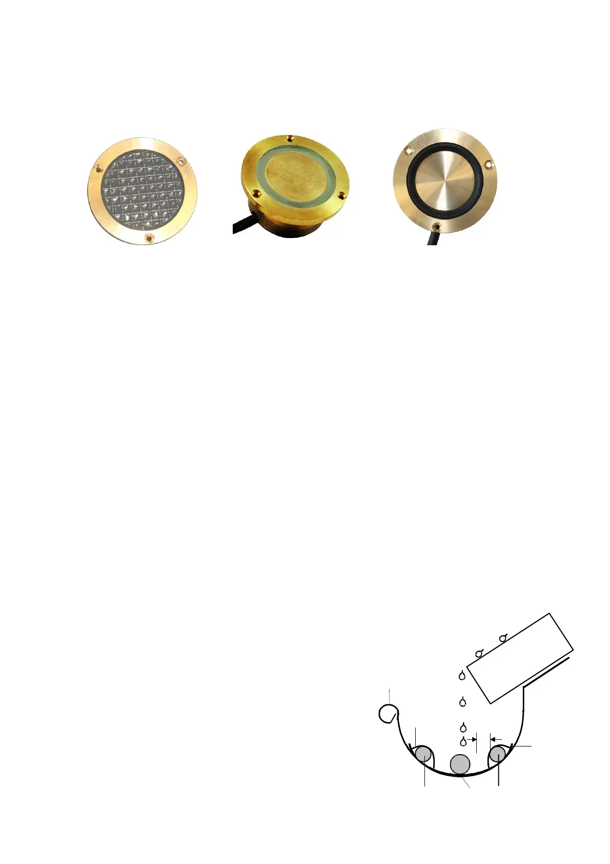
Technical data: Types 3352, 3353, 3355, 3356
Supply line: SL-Y11Y, length 6 m, 20 m, 50 m
resistant to microbes and oil according to DIN VDE 0472/9.21 para. 8036
Degree of protection: IP 68
Temperature resistance: –30 ...+75 °C
Sensor 3352/3353 Sensor 3355 Sensor 3356
Length of supply lines
The total length of the type SL-Y11Y supply line must not exceed 50 m. Provided that the clamping point
between the standard supply line and the extension is absolutely watertight and contact secure, the standard
supply lines may be extended by 6 m or 20 m up to the total length listed in the following overview. In order to
ensure operational safety, it is recommended to use a line extension only inside a building where it is dry.
Starting from the standard supply lines of 6 m or 20 m the total line length is as follows:
Standard line 6 m + Extension in 1.0 mm² (44 m) = Total length 50 m
Standard line 6 m + Extension in 1.5 mm² (66 m) = Total length 72 m
Standard line 6 m + Extension in 2.5 mm² (110 m) = Total length 116 m
Standard line 6 m + Extension in 4.0 mm² (176 m) = Total length 182 m
Standard line 20 m + Extension in 1.0 mm² (30 m) = Total length 50 m
Standard line 20 m + Extension in 1.5 mm² (45 m) = Total length 65 m
Standard line 20 m + Extension in 2.5 mm² (75 m) = Total length 95 m
Standard line 20 m + Extension in 4.0 mm² (120 m) = Total length 140 m
3. Sensor mounting in gutters, on rooftops and on satellite systems
(sensor type 3354)
The sensor must be installed in such a way that draining melt water runs off across the sensor. This ensures
that moisture is detected, if there is any.
In case the sensor is installed in a gutter or on a flat rooftop, it should be located as close as possible to the
downpipe or the drain In case it is used in connection with a parabolic aerial, the sensor should be placed
horizontally below the drip edge.
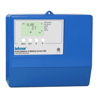
Installation position in the gutter
Explanation of the graphic:
1 cable tie for fastening the heat conductors
2 heat conductor
3 sensor 3354
4 distance of sensor and heat conductor minimum 2.0 cm
5 gutter
6 protruding roof surface