3 of 12 © 2010 D 313 - 11/10
Installation Location
When choosing the location for the control, consider the
following:
Keep dry. Avoid potential leakage onto the control.
RH 90% to 122°F (50°C) in a non-condensing
environment.
Do not expose to operating temperatures beyond 32-
122°F (0-50°C).
Provide adequate ventilation.
Keep away from equipment, appliances or other sources
of electrical interference.
•
•
•
•
•
Locate the control near zone valves if possible.
Provide easy access for wiring and viewing the
control.
Mount approximately 5 ft. (1.5 m) off the finished floor.
Install to wall using #10 x 1” wood screws. Wall anchors
are recommended when mounting to sheet rock, wall-
board or masonry.
•
•
•
•
Rough-In Wiring
Line Voltage Wiring
-----------------------------------------------------------------------------------
-----------------------------------------------------------------------------------
In most cases, the control can be mounted directly to a wall
without the need for any line voltage connections.
As an option, the control may be mounted to a 4” x 4”
electrical junction box so that the high voltage electrical
connections for the transformer are safely contained.
For ease of service, the circuit breaker or power disconnect
should be located in reasonably close proximity to the
equipment.
All line voltage wire connections are recommended to
be pulled inside a flexible or solid conduit. Always follow
proper wiring practices, building and electrical codes for
your jurisdiction.
Each cable must be pulled to the electrical junction box. It
is recommended to label each cable for easy identification.
All line voltage wires should be stripped to a length of 1/2”
(13 mm).
Pull a three conductor 14 AWG cable for the following
equipment:
Circuit Breaker or Power Disconnect (if applicable)•
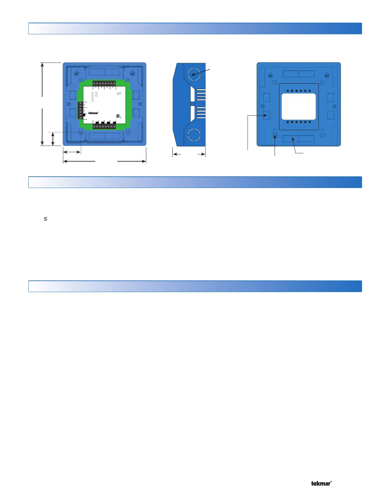
Physical Dimensions
5–1/2”
(140 mm)
5–1/2”
(140 mm)
1–1/8” (30 mm)
7/8”
(22 mm)
CL
Front View
1/2” Knock-out (x 4)
Ø 1/8” (3 mm)
7/8” x 1/2” (23 mm x 12 mm)
Knock-out (x 4)
1/2” x 5/8”
(12 mm x 16 mm)
Knock-out (x 4)
2–1/4”
(57 mm)
Input Power: 24 V (ac) ±10% 60 Hz
100 VA Max, Class 2
Control Load: 10 VA
End Switch: 24 V (ac) 2 A
Zone Output: 2 A (48 VA) per zone
4 A (96 VA) max total
Power
Zone 1
Zone 2
Zone 3
Zone 4
End Switch
Zone 1 Zone 2 Zone 3 Zone 4
tN2 tN2 tN2 tN2 tN2 tN2 tN2 tN2
tN2 Wiring Center 313
Four Zone Valves
tN4CX
Expansion
VlvC
Zone 1
VlvC
Zone 2
VlvC
Zone 3
VlvC
Zone 4
XC
Input Power
R
For use with tN2 thermostats only
Meets Class B: ICES & FCC Part 15
H8003A
End Switch
tN2
Use at least 167°F (75°C) conductors
Made in Canada
tektra 1034-01
Side View Back View