© 2010 D 313 - 11/10 6 of 12
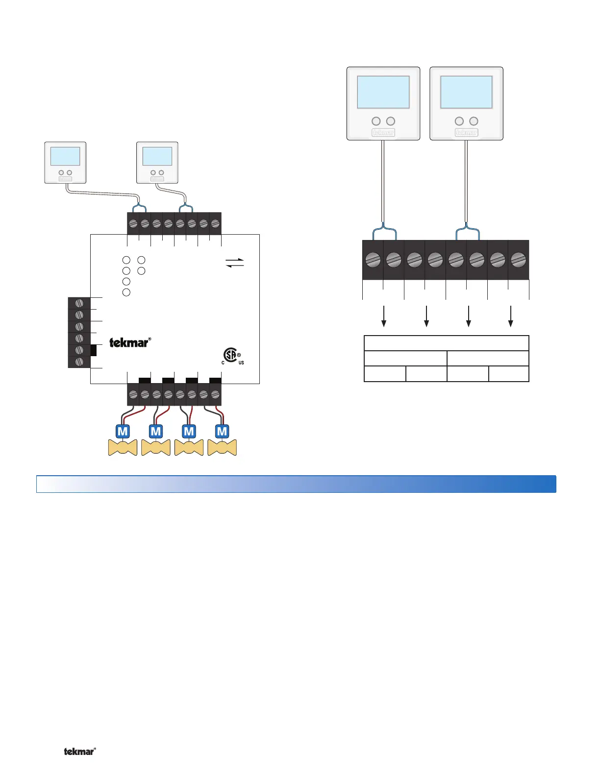
Two Stage tN2 Thermostats
A two stage thermostat is automatically detected when
connected to Zone 1 or Zone 3. If there is no tN2 thermostat
connected to Zone 2 or Zone 4, these outputs will automatically
operate the heating equipment for 2nd stage heat.
Power
Zone 1
Zone 2
Zone 3
Zone 4
End Switch
Zone 1 Zone 2 Zone 3 Zone 4
tN2 tN2 tN2 tN2 tN2 tN2 tN2 tN2
tN2 Wiring Center 313
Four Zone Valves
tN4CX
Expansion
VlvC
Zone 1
VlvC
Zone 2
VlvC
Zone 3
VlvC
Zone 4
Vlv
XC
Input Power
R
H8003B
End Switch
Input Power: 24 V (ac) ±10% 60 Hz
100 VA Max, Class 2
Control Load: 3 VA
End Switch: 24 V (ac) 2 A
Zone Output: 2 A (48 VA) per zone
4 A (96 VA) max total
For use with tN2 thermostats only
Meets Class B: ICES & FCC Part 15
tN2
Use at least 167°F (75°C) conductors
Made in Canada
tektra 1034-01
Zone Valves
tekmarNet
®
2 Two-Stage Thermostats
Testing the Control Wiring
Testing the Power
-----------------------------
-----------------------------
If the control Power light does not turn on, check the Input
Power wiring terminals using an electrical multimeter. The
voltage should measure between 21.6 to 26.4 V (ac). If the
voltage is below this range, measure the line voltage side
of the transformer. The voltage should measure between
103.5 to 126.5 V (ac).
Testing the Thermostats
----------------------
If the thermostat display turns on, this indicates that the
thermostat is operating correctly and there are no electrical
issues. In the event that the display is off, or the display is
cycling on and off, follow this procedure.
1. Remove the tN2 wires from the thermostat.
2. Use an electrical meter to measure DC voltage between
the tN2 terminals.
If the DC voltage is 0 V (dc) for 20 seconds, then there is
an open or short circuit in the tN2 wires. If the DC voltage
is 0 V (dc) for 10 seconds and then is 23 to 24 V (dc) for 5
seconds, this indicates the wiring is correct.
3. Connect the thermostat to the tN2 wires from a zone
on a House Control, Wiring Center, or Zone Manager.
4. If the thermostat display is off, or is cycling on and off,
move the thermostat to the next available zone on the
House Control, Wiring Center, or Zone Manager.
If the thermostat display remains permanently on, there
may be a fault with the previously tried zone on the House
Control, Wiring Center, or Zone Manager.
If the thermostat display continues to be off, or is cycling
on and off, there may be a fault on the thermostat.
If a fault is suspected, contact your tekmar sales representative
for assistance.
Testing the Zone Output
----------------------
Turn up the thermostat connected to Zone 1 until it calls
for heat showing the H1 on the display. Using an electrical
meter, measure the voltage between the zone valve and
the common (C) terminals. The voltage should measure
between 21.6 V (ac) and 26.4 V (ac). Repeat for Zones 2,
3, and 4.
Two-Stage Thermostat Wiring
------------------------------------------------------------------------
------------------------------------------------------------------------
Zone 1 Zone 2 Zone 3 Zone 4
tN2 tN2 tN2 tN2 tN2 tN2 tN2 tN2
Two-Stage Terminal Designation
Zone 1 Zone 3
Stage 1 Stage 2 Stage 1 Stage 2